Update : I’ve realised that changing the pull up resistor to a pull down resistor means that the circuit will react better if the fan 12V is applied before the Arduino power supply is activated. As such, I’ve moved my resistor so that it is now between the gate pin and ground.
Having a bit of spare time, I decided to transfer a load of files from my previous computer (a Mac) to my new computer (Linux). As I had a lot of data from a number of hard disks to move, I decided the best method would be using an external eSATA drive. Thankfully, due to a stalled home build SAS project I started a few years ago, I have a couple to hand. The are branded as SUUNION SUBE3ZW enclosures, the “E” being optional and meaning they support eSATA. Helpfully they come with an internal SATA to eSATA expansion slot adapter and my motherboard has a feature in the BIOS that lets you turn hot swapping on for a SATA port. Without the latter, I’d have needed to power down my computer every time I wanted to switch in a different disk. These SUUNION enclosures have almost no internet presence, but were really cheap about 7 or 8 years ago when I bought them.

SUBE3ZW Enclosure
While transferring data, I noticed in the S.M.A.R.T data for the drive that it was getting quite warm and had reached 50°C. I looked up the temperature ratings for the drive in question (a 1.5TB Seagate Barracuda) and discovered they were rated to a maximum temperature of 50°C… oh dear. It seems that it isn’t great to run some (7200rpm) disks in fan-less enclosures.
Initially I grabbed my home made soldering air filter (120mm computer fan, connected through an inline power switch to a 12v wall-wart) without the filter to cool it down, but since I had time to kill waiting for the file transfers and the fan was quite loud considering my girlfriend was trying to work in the same room, I started looking into adding some speed control.
The Circuit
Parts used:
- 1x Arduino Pro Mini (anything similar will do, including an UNO – note that devices with different main chips will have different PWM requirements and the code will not work without changes).
- USB to UART board, like this one.
- 1x 2N7000 MOSFET – an excellent all-rounder MOSFET.
- 1x 1N4007 Diode – massively over-specified, but I have a bag of them and they cost very little. Any similar diode will do (I suspect anything from the 1N400x range is fine).
- 1x 10k Resistor (0.5W).
- Breadboard – the circuit could be built on protoboard for a more permanent solution.
- Some wire, suitable for use in breadboard.
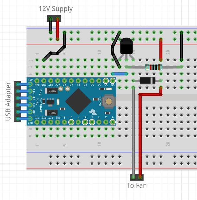
Breadboard Layout of Fan Controller
Three things to take care of :
- Do not connect the 12V supply to the microcontroller – this will damage it, and potentially any connected computer.
- Note the pins on the left of the Arduino are reversed on some clones – my device has the pins in the opposite order to those shown in the drawing above. If your Arduino matches the drawing above and you are using the same USB adapter as I am, your adapter should be face down into the table. If your Arduino and USB adapter are both identical to mine, the adapter should be face up.
- Ensure the USB adapter power jumper is set to 5V if you are using a 5V arduino. The circuit should also work with a 3.3V Arduino (the minimum gate trigger voltage for the 2N7000 MOSFET is 3V), although ensure all voltages are correct.
The following is a rough schematic – all ground points need to be linked (as per the breadboard layout).
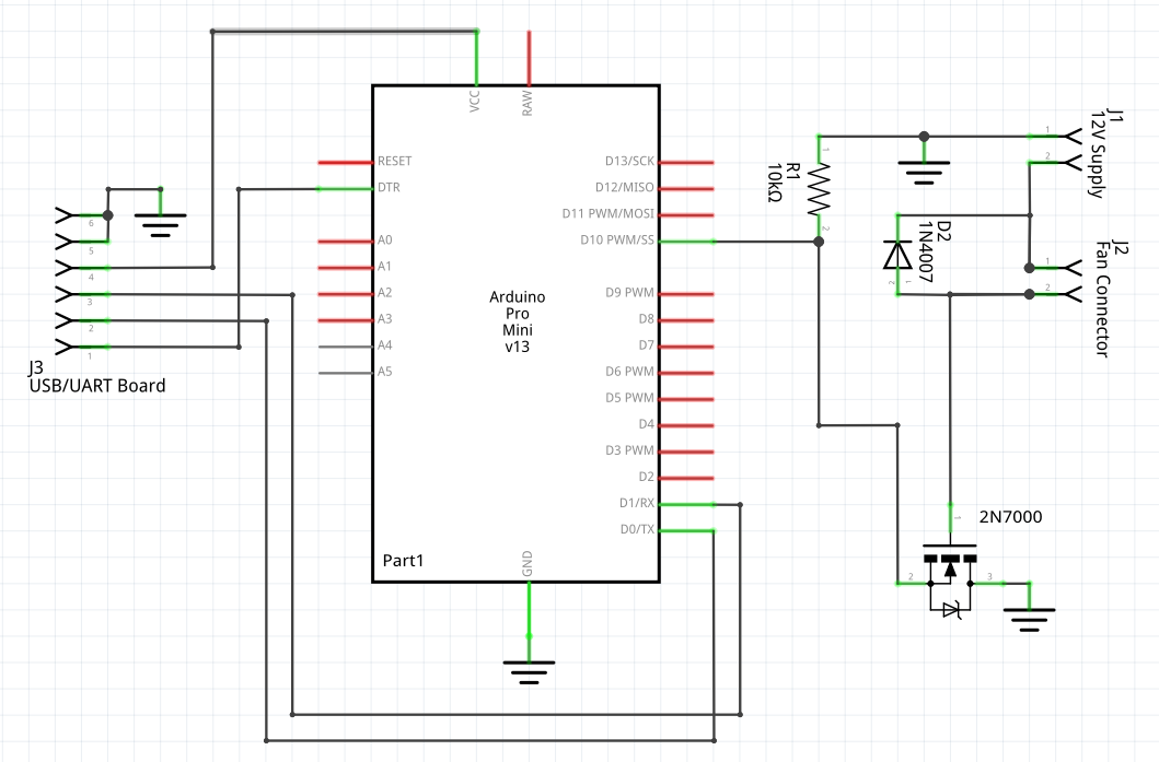
Fan PWM Controller Schematic
The 10k resistor (R1) is a pull down resistor and is needed to control the input to the MOSFET – without this the MOSFET might get very hot and fail if the Arduino is removed or if the connected pin is set as an input. The resistor is best located as close to the MOSFET gate pin as possible. The Diode (D2) (yes, the numbering system is wonky) dissipates the back EMF generated by the fan when the supply is cut. The MOSFET (Q3) switches the 12V supply (on the low side of the fan) based on the PWM signal from pin 10 on the Arduino, while effectively isolating the Arduino from the 12V and preventing damage. On its own, the Arduino would not be able to provide 12V, and can not provide the 180mA required by the fan I am using. The 2N7000 MOSFET is actually able to switch voltages up to 60V, although that is more than my fan can handle.
Once I had programmed the Arduino, I disconnected the DTR pin from the USB adapter to prevent my computer from resetting the Arduino constantly – this will not be possible so easily if you’re using an Arduino Uno. The trick I like to use to do this with an Arduino Pro Mini is as follows :
- When soldering headers onto the Arduino Pro Mini, replace the supplied male header with a female header – this makes programming the boards much easier as the USB adapter has male headers.
- Once programming is completed and you do not want the board to reset when a serial connection is established, place a 5 pin female header with extended pins (wire wrap / pass through style) between the Arduino and the USB adapter, taking care that the missing pin is the DTR (“GRN”) pin.
Note that it is still possible to program the board in this condition if you carefully press the reset button at the exact right moment. Also note that I actually use a 6 pin header with one pin trimmed off (because it reminds me what the header is for when I see it lying on my desk and I don’t throw it away).
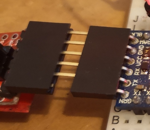
Disable Reset
The Fan
I’ve used a small 40x40x20mm fan that I had in a cupboard. Other fans will be fine, although note that at these high PWM frequencies, I did have some difficulty with one cheaper fan where it was struggling to start.
To help with this, I’ve modified my Arduino software to give the fan a short burst of maximum speed (a fraction of a second) whenever the fan speed changes to help ensure the fan is running – while there is still a PWM duty below which the fan will not run, I have found that this specific fan generally runs down to as low as 50/255 (~20%) of full. Note the PWM duty does not correspond to fan speed – most of the variation available is between 200 and 255 (~80% to ~100%).
It is recommended that you put a switch in the 12V supply so that it is possible to turn off the fan easily. An improvement might be to take the pull up supply from the 12V using a regulator to generate 5V (for the whole circuit). Care should be taken to not back feed the computer’s USB with a slightly different 5V supply. There is a built in regulator on the Arduino Pro Mini which could be used for this, where 12V could be provided to the “RAW” pin, although 12V is the maximum recommended voltage for this regulator and it might get warm with sustained use. This would be a good option if you were also measuring temperatures using the Arduino in another application.
The Stand
A quick and easy way to make an adjustable stand for a fan is to use a piece of stiff wire, bent into shape through two of the fan’s screw holes. I’ve used a piece of stainless steel welding wire as can be seen in the following photograph.
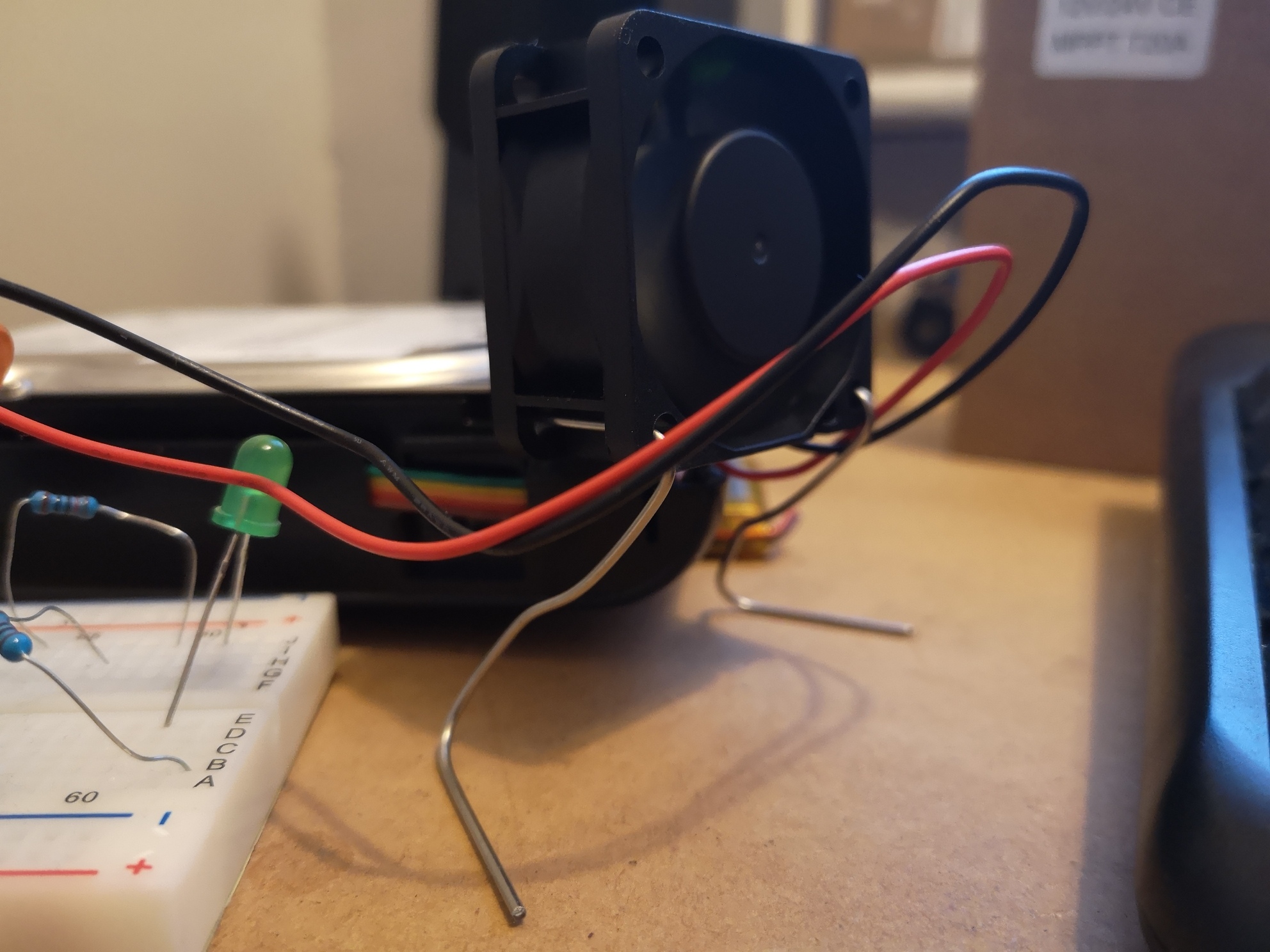
Fan and Stand
The wire is in one piece and crosses the front of the fan between the two screw holes (on the other side of the fan from the camera). Pliers will make bending the wire easier.
Arduino Software
/******************
 * Arduino High Frequency PWM Fan Controller Code
 * https://elephantandchicken.co.uk/stuffandnonsense
 * Circuit :
 * Connect the gate of a 2N7000 to arduino pin 10.
 * Connect a 10k Resistor between the gate and 5V.
 * Connect the source pin to ground.
 * Connect a 1N4007 diode between the drain pin and 12V with the band facing 12V.
 * Connect a fan between the 12V rail and the drain pin.
 * Remember to connect the grounds for the 12V and 5V circuits!
 * Do not mix 12V and 5V!
 * If in doubt, details of the circuit and software for controlling from linux
 * are on my website
 *******************/

int fan = 10; // set fan output pin
int fanspeed = 255; // start full speed
// for SerialEvent
String inputString = "";
boolean stringComplete = false;

void setup() {
  // set the fan pin as an output
  pinMode(fan, OUTPUT);

  // adjust the PWM speed to make it fast enough that you can't hear it
  // see : https://playground.arduino.cc/Main/TimerPWMCheatsheet
  TCCR1B = (TCCR1B & 0b11111000) | 1; // hard coded for pins 9 or 10

  // Start serial - doesn't need to be very fast
  Serial.begin(9600);
  Serial.println("\nPWM Fan Controller Started");

  // For safety, as we don't know what is happening yet, turn the fan onto full
  digitalWrite(fan, HIGH);
}

void loop() {
  if(stringComplete){ // We've recieved a message
    // reset the serial variables ready for the next message
    String msg = inputString; // store locally so serialEvent can get back to capturing input
    inputString = "";
    stringComplete = false;

    if(msg.startsWith("s")){ // "set" command
      if(fanspeed!=msg.substring(1).toInt()){ // if the requested speed is different...
        fanspeed = msg.substring(1).toInt(); // update the fan speed
        digitalWrite(fan, 1); // these two lines help with a stalled fan...
        delay(50); //             by ramping the speed to full with no PWM for a short period
        analogWrite(fan, fanspeed); // set the new PWM duty
      }
      Serial.println(fanspeed); // confirm the new speed to the host
    }else if(msg.startsWith("c")){ // "check" command
      Serial.println(fanspeed); // the host has asked what PWM duty we're currently using
    }
  }
}

void serialEvent() {
  // Standard serial code from "SerialEvent" example
  while (Serial.available()) {
    // get the new byte:
    char inChar = (char)Serial.read();
    // add it to the inputString:
    inputString += inChar;
    // if the incoming character is a newline, set a flag
    // so the main loop can do something about it:
    if (inChar == '\n' || inChar == '\r') {
      stringComplete = true;
    }
  }
}
Linux Software
Due to the limitations of my knowledge in various languages, I’ve used a mixture of bash and python as well as an existing piece of software to achieve what I wanted. My objectives were to continually monitor the external hard disk temperature, and set the fan speed based on this temperature. First things first, I used the “Disks” utility on Ubuntu to identify the external disks location – for exampe : /dev/sdc
The path “/dev/sd*” (where * is a letter of the alphabet) should exist for each connected disk, the similar files with a number on the end as well represent individual partitions and we are not concerned with these at the moment.
Next identify the serial port – with the adapter connected, type “ls /dev/ttyUSB*” at the command line. If you’re lucky, you will get a single result called “/dev/ttyUSB0” or similar. Note this can and does change, especially when you’re plugging and unplugging USB adapters, so you might need to re-check. If the previous command doesn’t return anything, try “ls /dev/tty*”. This will return a long list – ignore all entries which are just “/dev/tty#”, “/dev/ttys#” or “/dev/ttyprintk” where “#” is a number. Look at what else is there… unplug the adapter and run the command again. What is different? Plug the adapter back in again – does it re-appear? Whatever appears and disappears when you plug and unplug the adapter is the serial port you are looking for. As mentioned, the number might change as you are messing around.
Make a note of the disk path and serial port path. Mine are “/dev/sdc” and “/dev/ttyUSB0”.
Software which might need installing :
- watch (sudo apt-get install watch) – allows you to run a command every n seconds
- hddtemp (sudo apt-get install hddtemp) – reports the identified disk’s temperature
- python (sudo apt-get install python) – programming language, probably already installed
- pyserial (pip install pyserial) – a python library to work with serial ports
Create a folder and move into it (to do this in the command line, use mkdir HDDTemperature && cd ./HDDTemperature to create a folder called HDDTemperature at your current location). Create three plain text files called hddFanControl.sh, hddFanControl.py and run.sh using your favourite text editor. Enter the following scripts into each respectively :
# Script to check a hard disks temperature, and send a fan speed over serial
# Usage :
# run.sh /dev/sd* /dev/ttyUSB*
# Ensure run.sh, hddFanControl.sh and hddFanControl.py are all in the current
# active directory.
# Note you need permission to access both the hdd and the serial port
# Note you'll need to disable reset on the MCU
# Serial fan controller should accept speed settings in the format s[0-255]
# where [0-255] is the pwm value between 0 and 255. Note most speed control
# is between 200 and 255, and often a fan needs 255 to start (due to the high
# pwm frequency (I'm using 31khz I think - there aren't many options on an 8
# bit AVR, just 60khz and 30khz which don't create noise. 60khz struggled to
# start the motor. AVR code I used to set the pwm speed was :
# TCCR1B = (TCCR1B & 0b11111000) | 1;
# and I'm using pin 10 (this command would also work for pin 9)
# be warned that messing with these pwm settings impacts other timing commands
#
# https://elephantandchicken.co.uk/stuffandnonsense
# 12/12/2018

# hdd location
VARHDD="$1"
# serial port
VARSER="$2"

TEMPERATURE=`hddtemp $VARHDD | grep -oh "..°C" | grep -ohE "[0-9]{1,4}"`
echo "Selected disk temperature is $TEMPERATURE°C"

python ./hddFanControl.py $VARSER $TEMPERATURE
# Script to check a hard disks temperature, and send a fan speed over serial
# Usage :
# run.sh /dev/sd* /dev/ttyUSB*
# Ensure run.sh, hddFanControl.sh and hddFanControl.py are all in the current
# active directory.
# Note you need permission to access both the hdd and the serial port
# Note you'll need to disable reset on the MCU
# Serial fan controller should accept speed settings in the format s[0-255]
# where [0-255] is the pwm value between 0 and 255. Note most speed control
# is between 200 and 255, and often a fan needs 255 to start (due to the high
# pwm frequency (I'm using 31khz I think - there aren't many options on an 8
# bit AVR, just 60khz and 30khz which don't create noise. 60khz struggled to
# start the motor. AVR code I used to set the pwm speed was :
# TCCR1B = (TCCR1B & 0b11111000) | 1;
# and I'm using pin 10 (this command would also work for pin 9)
# be warned that messing with these pwm settings impacts other timing commands
#
# https://elephantandchicken.co.uk/stuffandnonsense
# 12/12/2018

import time
import serial
import sys
from math import log

# How aggressive to make the fan curve? 0.4 is normal, 0.1 ramps up quickly
# at the start then levels off, 1 is linear (pwm duty, not cooling), 2 mainly
# ramps at the top end (would be basically off until the temp was at the top)
fanCurve = 0.4

Temperature = int(sys.argv[2])
maxTemp = 50
minTemp = 30
tempRange = maxTemp-minTemp

tempLift = Temperature-minTemp

if tempLift <= 0:
	pwmDuty = 0
elif tempLift >= tempRange:
	pwmDuty = 255
	print "\nWarning! Hard Disk is hot!"
	print "Disk is currently : " + str(Temperature) + " degrees C"
else:
	var1 = (tempLift**fanCurve)
	var2 = (tempRange**fanCurve)
	pwmDuty = int(255*var1/var2)
	print "\nCurrent Temperature : " + str(Temperature)
	print "Current Target PWM setting : " + str(pwmDuty)

ser = serial.Serial(
	port=str(sys.argv[1]),
	baudrate=9600,
	parity=serial.PARITY_NONE,
	stopbits=serial.STOPBITS_ONE,
	bytesize=serial.EIGHTBITS
)

ser.isOpen()

#flush with an empty line
ser.write('\n')
time.sleep(0.1)
ser.flushInput()

# moved the following into the mcu
#if pwmDuty > 0:
#	# make sure we are not stalled
#	ser.write('s255\n')
#	time.sleep(0.1)

#check current setting
ser.write('c\n')
time.sleep(0.1)
out = ''
while ser.inWaiting() > 0:
        out += ser.read(1)
if out != '':
        print "\nMCU previous PWM was : " + str(int(out))

#send pwm setting
ser.write('s' + str(pwmDuty) + '\n')

# pause and see if there was a response
time.sleep(0.1)
out = ''
while ser.inWaiting() > 0:
	out += ser.read(1)
if out != '':
	print "MCU current PWM is : " + str(int(out))

ser.close()
exit()
# See comment in hddFanControl
# https://elephantandchicken.co.uk/stuffandnonsense
# 12/12/2018

watch -n60 ./hddFanControl.sh $1 $2
Back at the command line, enter the following three commands to convert the files into runnable software :
chmod +x ./hddFanControl.sh
chmod +x ./hddFanControl.py
chmod +x ./run.sh
To run the software, ensure that the Arduino is powered and connected to the computer through the USB adapter, then apply power to the fan. The fan should start at maximum speed.
You’ll need the disk and serial port paths from above to run the software, once you have them and have checked they are correct, enter the following (but using your hard disk and serial port) :
sudo run.sh /dev/sdc /dev/ttyUSB0
If everything works correctly, you should see something like the following, which will update every 60 seconds :
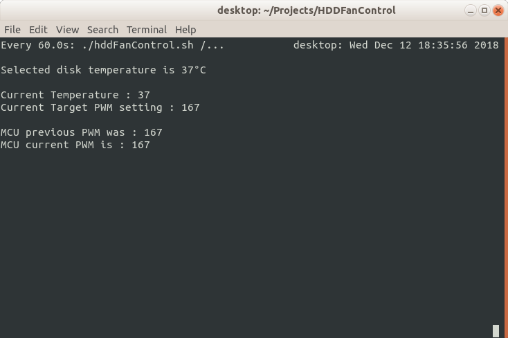
Screenshot
To stop the program, press Ctrl-C. Once you’re finished with the fan, power down the 12V fan supply and the Arduino.
Changing Parameters
To change the temperature update frequency, you will need to edit the file run.sh. The interval between measurements is represented by the 60 in “-n60” and can be replaced by other durations in seconds. To change the interval to be two minutes, run.sh would need to be changed to :
# See comment in hddFanControl
# https://elephantandchicken.co.uk/stuffandnonsense
# 12/12/2018

watch -n120 ./hddFanControl.sh $1 $2
All other parameters which can easily be modified are contained within the python file hddFanControl.py and allow the “normal” temperature range, and temperature/PWM response curve to be modified. Normal temperatures are defined by the variables maxTemp and minTemp (set to 50 and 30 respectively in the provided code). When the measured temperature is outside of this range, the fan duty will be pegged at either 0% (30°C or less) or 100% (50°C or more). These values can be modified the shift the operating temperature range if needed.
The temperature/PWM response curve is modelled as the temperature above the minTemp raised to a power (a variable called fanCurve). By adjusting the power, the characteristic of the curve can be adjusted. By default I am using a power of 0.4, which works well for my use case. The following plot shows the impact of varying the value of fanCurve.
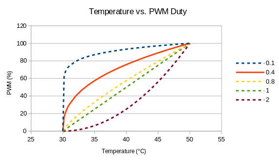
PWM Plot
Adjusting the value allows the user to modify how early or late the % duty increases. Note that this only relates to the PWM duty and not fan speed. I have generally found that most of the variation in fan speed is observed in the last 25% of PWM duty.
Note that modifying the fanCurve variable is the best way of adjusting the balancing temperature of a specific state. Using 0.4, I was able to achieve a stable 37°C disk temperature, which was considered satisfactory, and comparable to the temperatures of my internal hard disks.
Conclusions
If you’re wondering, the file copy still hasn’t finished. (Update : it finally has).