Using AVRprog2 and an EasyAVR5A with the Arduino IDE
A few years back I bought myself a mikroe EasyAVR5A from the discount bin of an online store. Sadly, at the time, there was no way to use the built in USB programmer from any OS other than Windows, so I resorted to programming the board through a USBasp.
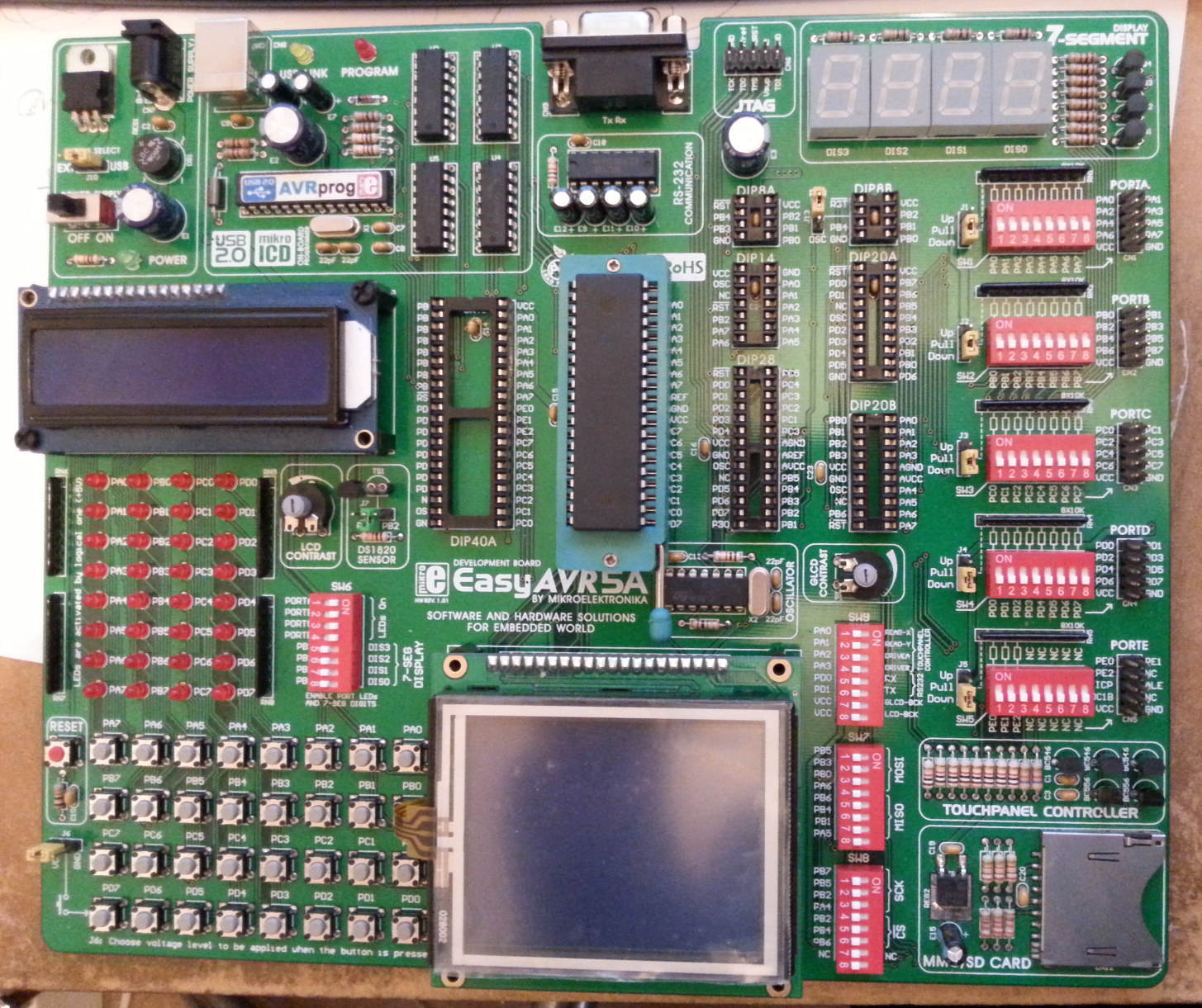
The mikroe EasyAVR5A
Jump forwards a while and a helpful university produced a Linux (and Mac) program compatible with the built in USB programmer. This can be found here. I have been using this software for a while and am very happy that it exists. To use it with the Arduino IDE, you need to add the MCUs you’re using (if you use an ATMega328p you can skip this as it is the standard chip in an Arduino Uno, although you will need to add it to the list of xml files which describe chips for the AVRprog2 software, described later for the ATMega32), build the project with “verbose” turned on in preferences, copy the path to the final mentioned .hex file, and paste it into the command line with the command to program the board. A little bit of a faff.
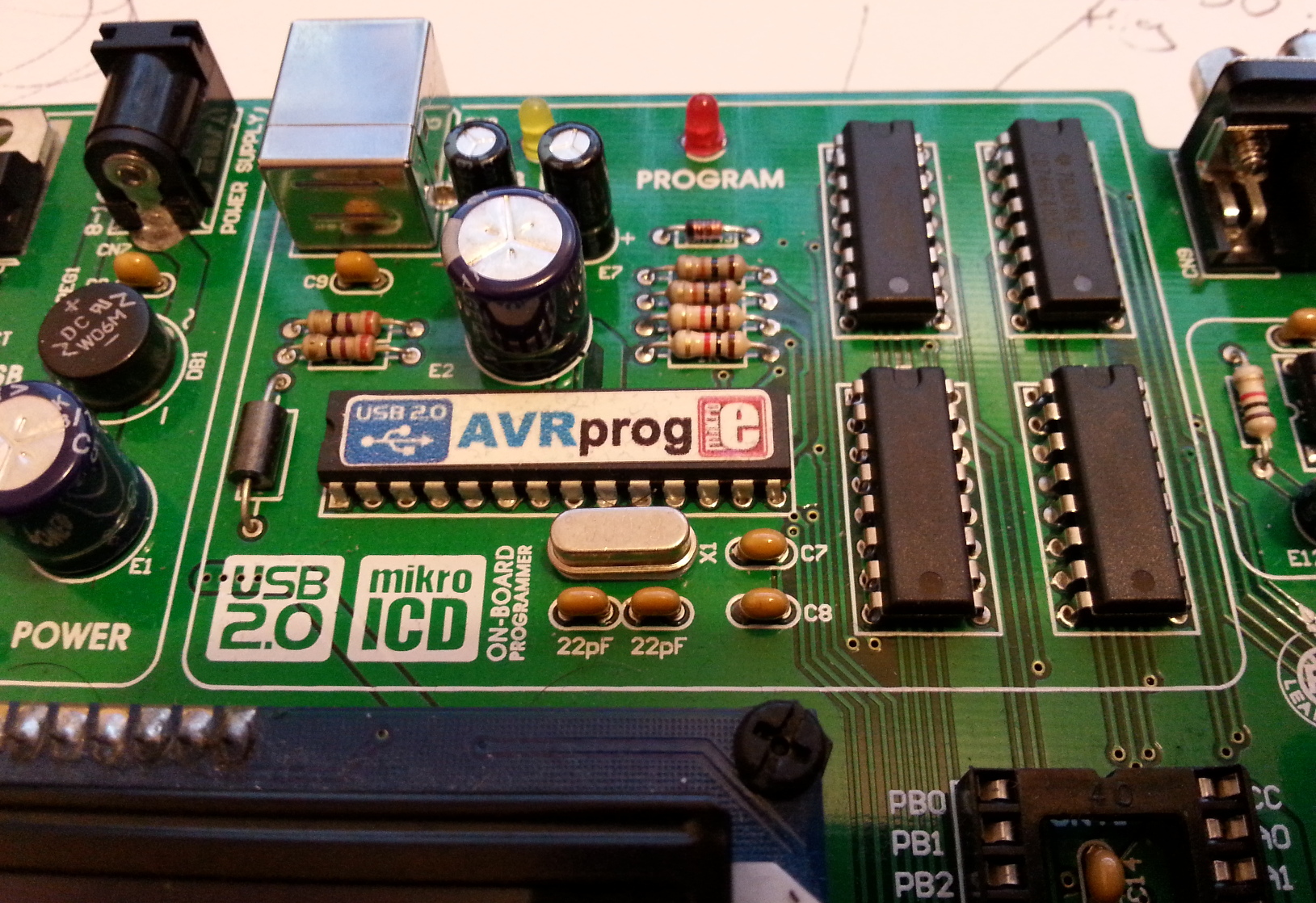
The mikroe AVRprog2
Messing about today I set myself a little challenge to see if I could add the avrprog2 program as a programmer within the Arduino IDE – I managed to get it working, so here are the directions on how. This should apply to other boards that use the mikroe AVRprog2 interface (labelled as AVRprog on the board, which causes confusion as there is a parallel interface programmer called the same).
1. Download, compile and install the github avrprog2 project. You can mostly follow their instructions, except you have to run autogen.sh before anything else (otherwise the configure script doesn’t exist). The listed dependencies are not helpfully named (some aren’t the package names), but a bit of googling gets it working. For reference, I ran the following commands to install :
sudo apt-get install libusb-1.0-0-dev
sudo apt-get install binutils-dev
sudo apt-get install libboost-all-dev
sudo apt-get install doxygen
sudo apt-get install graphviz-dev
sudo apt-get install graphviz
./autogen.sh
./configure
make
sudo make install
2. Open the folder called “config”. Copy, then edit the file “atmega16.xml” to a file called “atmega32.xml” and then replace the contents with the following :
<device>
	<name>ATmega 32</name>
	<signature>0x1e9502</signature>
	<flashSize>32768</flashSize>
	<flashPageSize>128</flashPageSize>
	<eepromSize>1024</eepromSize>
	<numOfFuses>2</numOfFuses>
</device>
You don’t need to do this if you don’t plan to use the ATMega32A part, but I did and might as well include it. Once edited, save and copy to the folder “/usr/local/share/avrprog2/”. You’ll need super user permissions to do this.
I’ve uploaded a few more config files in this post. Note that I’ve included the default ones for reference. I’ll add more with time as I test more chips.
3. Install MightyCore as per the instructions on the github page.
4. Add the following to the MightyCore platform.txt file (mine was located in “~/.arduino15/packages/MightyCore/hardware/avr/1.0.8” – you can find the correct folder by going to Preferences in the IDE, then clicking on the link under “More preferences can be edited directly in the file…”, then navigating through ./packages/MightyCore/hardware/avr/1.0.8) :
# avrprog2 entry
tools.avrprog2.cmd.path=/usr/local/bin/avrprog2
tools.avrprog2.cmd.path.linux=/usr/local/bin/avrprog2

tools.avrprog2.upload.params.verbose=-d
tools.avrprog2.upload.params.quiet=
tools.avrprog2.upload.pattern="{cmd.path}" -m {build.mcu} -f {build.f_cpu} --flash w:{build.path}/{build.project_name}.hex

tools.avrprog2.program.params.verbose=-d
tools.avrprog2.program.params.quiet=
tools.avrprog2.program.pattern="{cmd.path}" -m {build.mcu} -f {build.f_cpu} --flash w:{build.path}/{build.project_name}.hex
I placed it above the line “# USB Default Flags”.
5. Add the following to the top of the MightyCore programmers.txt file :
# avrprog2 entry
avrprog2.name=avrprog2
avrprog2.communication=usb
avrprog2.protocol=avrprog2
avrprog2.program.protocol=avrprog2
avrprog2.program.tool=avrprog2
6. Save both modified files, restart the Arduino IDE and… you should see a new entry called “avrprog2” in the Tools>Programmer menu.
7. Load your program, select the correct MightyCore chip (the board comes with an ATMega16), select the avrprog2 and other various settings for the MCU then…
8. Shift click the Upload button. If all goes well you should see the compile and then your program loading into the chip. I find I can’t program the board twice without powercycling between, and sometimes it doesn’t find the board for some reason (but that is the same when using the programming software from the command line.
Hope someone finds these instructions useful – they have been written at speed because I have somewhere to be. I may return to clean them up and add some pictures at a later date!
Note that I’ve not currently made modifications which allow you to flash the bootloader (I’ve not done anything that writes the fuses). The following two commands seem to work for Internal 8mhz and external crystal respectively :
8mhz Internal Clock :
avrprog2 -m atmega32 --fuses w:f4,d6

16mhz External Crystal :
avrprog2 -m atmega32 --fuses w:c0,d6
Good luck!
I found this page useful while making this modification : https://github.com/arduino/Arduino/wiki/Arduino-IDE-1.5-3rd-party-Hardware-specification
As well as looking at the Digistump platform.txt and programmer.txt files (started by making a copy of their platform.txt contents).
I’m also thankful for a point in the right direction from blathijs on the Arduino IRC.