Introduction
The following details how to put together a system to automatically take and upload photos using a webcam attached to a small Linux computer. I have previously built a system that automatically took a photo when a user connected to a webpage, but this time I think I will just schedule photos to be taken at a fixed time interval for simplicity. This also means that I can upload to my hosting provider’s servers and share links without exposing my home IP.
This should provide a convenient way to check on your pets when you’re feeling bored at work. I will use specific hardware for this project, but the solution will be very portable. The reason for this is that I’m planning to use the operating system “Armbian“, a variant of Debian, primarily used on ARM based Single Board Computers (SBC). Armbian will run on a huge number of different boards and is similar in compatibility to Raspbian, the default operating system for the Raspberry Pi. I expect that, with a minimum of changes, the instructions here will work on most of these supported boards, and others.
Hardware
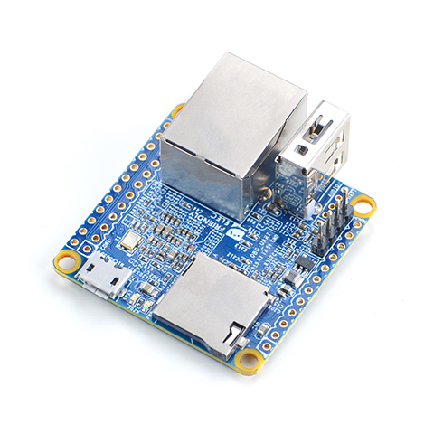
NanoPi NEO
I will be using the following hardware :
- A Friendly ARM NanoPi NEO with 512M of RAM. Mine is a v1.1
- A micro SD card
- An ethernet cable, a passive POE injector and splitter, plus an adapter to connect to the power connector on the NanoPi and a mains to 5v adapter for the other end
- A USB webcam – almost anything will do. Mine is out of a “smart” birdbox
- Not really hardware, but somewhere to upload the pictures is also required
- Optional – A case for the NanoPi, or even better, a waterproof case for the NanoPi and the webcam
- Optional – An infrared light, for nighttime viewing
While setting everything up, the following are needed / will be useful :
- Another computer to remotely set things up
- A USB to UART (3.3v in my case) adapter plus cable
- A card reader for the micro SD card if required
- A USB power adapter
It is worth noting that my selected board doesn’t have a display output – set up would be simpler if it did, but once it is in place there is no need for a display.
Step 1 – Setting up the card
I downloaded a disk image from https://www.armbian.com/nanopi-neo/ specifically the legacy kernel version 5.30. There are links to tools to flash an image for various platforms, as I’m using Linux, I tend to just use the command line tool dd to clone the image to an SD card this method should also work on MacOS X.
The file I downloaded is a .7z compressed archive. The file I’m interested in is called “http://wiki.friendlyarm.com/wiki/index.php/NanoPi_NEO”. I will extract this to somewhere handy.
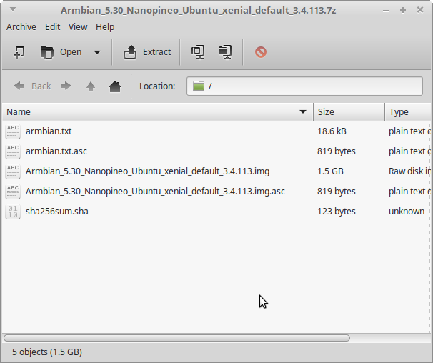
Armbian Archive Contents
To write the image to an SD card, unmount it (carefully, don’t overwrite the wrong disk), navigate to the folder where the disk image is located using cd and use the following command :
sudo dd if=./<imagename.img> of=/dev/<drive> bs=4M && sync
Replace <imagename.img> with the name of of your disk image and replace <drive> with the name of your drive. My SD card was called mmcblk0. You can probably find the name of the device by running the command ‘df -h’ before, and then again after, placing the device in the computer. SD cards often start with mmcblk, while other disk types might be sda, sdb, sdc etc. Take extra care as the chances are that sda and similar are disks in your computer. Make sure you’re certain before you overwrite anything! The bs argument means block size. if is the source, of is the destination. The final part, “&& sync” is a second command tacked on the end to ensure that the content of the SD card (and all other drives) are synchronised and fully up to date.
There isn’t much feedback from the command dd, but once it is finished it spits out a bit of info about the transfer and returns to the command prompt. It is now OK to eject the SD card and place it in the NanoPi.
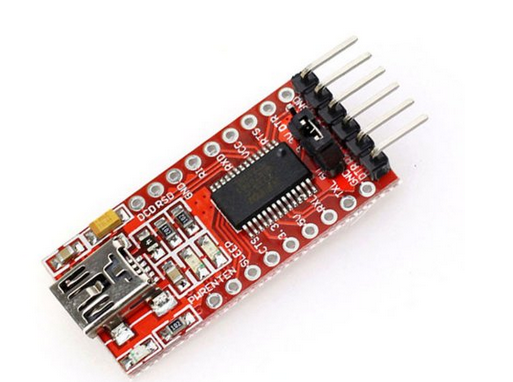
USB to UART Adapter
The UART adapters I like (because they’re cheap) have a jumper to select between 3.3v and 5v. Make sure you check this before plugging it in. It is worth getting these adapters as they let you program all sorts of MCUs as well as use the serial debug ports on all sorts of devices.
Plug in an ethernet cable, the UART (set to 3.3v for this board). For my v1.1, the UART port is against the USB port, this has moved for later versions of the board. For my board, GND is the furthest from the edge of the board, I have left the next pin (5v) unconnected. The next two pins are TX and RX in that order. Remember to connect the SBC’s RX to the adapter’s TX and SBC’s TX to the adapter’s RX. The following is the pinout for newer versions of the NanoPi Neo. Be sure to use the correct pinout for your device.
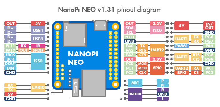
NEO Pinout
With the USB to UART plugged into a computer, you will need to open a serial terminal. On Linux, the simplest way is to use the command “screen” if it is installed (it usually is). On Windows, Putty would be my preference. “screen” may be installed on MacOS X, I’m not sure. If it isn’t google search for a MacOS serial terminal program and see what the internet recommends.
To find the correct port and open the connection, use the following commands at the command line on Linux. Plug the USB to UART adapter into the computer after typing the command on line 1 (not the example prompt I’ve included, that is, only type starting with ls… etc) :
exampleuser:~$ ls /dev/tty*
/dev/tty    /dev/tty19  /dev/tty3   /dev/tty40  /dev/tty51  /dev/tty62
/dev/tty0   /dev/tty2   /dev/tty30  /dev/tty41  /dev/tty52  /dev/tty63
/dev/tty1   /dev/tty20  /dev/tty31  /dev/tty42  /dev/tty53  /dev/tty7
/dev/tty10  /dev/tty21  /dev/tty32  /dev/tty43  /dev/tty54  /dev/tty8
/dev/tty11  /dev/tty22  /dev/tty33  /dev/tty44  /dev/tty55  /dev/tty9
/dev/tty12  /dev/tty23  /dev/tty34  /dev/tty45  /dev/tty56  /dev/ttyGS0
/dev/tty13  /dev/tty24  /dev/tty35  /dev/tty46  /dev/tty57  /dev/ttyS0
/dev/tty14  /dev/tty25  /dev/tty36  /dev/tty47  /dev/tty58  /dev/ttyS1
/dev/tty15  /dev/tty26  /dev/tty37  /dev/tty48  /dev/tty59  /dev/ttyS2
/dev/tty16  /dev/tty27  /dev/tty38  /dev/tty49  /dev/tty6   /dev/ttyS3
/dev/tty17  /dev/tty28  /dev/tty39  /dev/tty5   /dev/tty60
/dev/tty18  /dev/tty29  /dev/tty4   /dev/tty50  /dev/tty61
exampleuser:~$ ls /dev/tty*
/dev/tty    /dev/tty19  /dev/tty3   /dev/tty40  /dev/tty51  /dev/tty62
/dev/tty0   /dev/tty2   /dev/tty30  /dev/tty41  /dev/tty52  /dev/tty63
/dev/tty1   /dev/tty20  /dev/tty31  /dev/tty42  /dev/tty53  /dev/tty7
/dev/tty10  /dev/tty21  /dev/tty32  /dev/tty43  /dev/tty54  /dev/tty8
/dev/tty11  /dev/tty22  /dev/tty33  /dev/tty44  /dev/tty55  /dev/tty9
/dev/tty12  /dev/tty23  /dev/tty34  /dev/tty45  /dev/tty56  /dev/ttyGS0
/dev/tty13  /dev/tty24  /dev/tty35  /dev/tty46  /dev/tty57  /dev/ttyS0
/dev/tty14  /dev/tty25  /dev/tty36  /dev/tty47  /dev/tty58  /dev/ttyS1
/dev/tty15  /dev/tty26  /dev/tty37  /dev/tty48  /dev/tty59  /dev/ttyS2
/dev/tty16  /dev/tty27  /dev/tty38  /dev/tty49  /dev/tty6   /dev/ttyS3
/dev/tty17  /dev/tty28  /dev/tty39  /dev/tty5   /dev/tty60  /dev/ttyUSB0
/dev/tty18  /dev/tty29  /dev/tty4   /dev/tty50  /dev/tty61
exampleuser:~$ screen /dev/ttyUSB0 115200
The second type you enter the command ls /dev/tty*, there will be a single extra entry. This is the device you plugged in. In my case, it was called /dev/ttyUSB0. The third command, screen /dev/ttyUSB0 115200 opens a serial terminal at 115200 baud. The baud is the communication speed. I know that my NanoPi uses 115200 because I guessed what it used and got it right on my second try. It would have taken longer to look it up.
You will be rewarded with a blank screen. Plug the NanoPi into a power source (of the correct type) and a large amount of text should scroll past. Once it finishes, you will be presented with a login prompt. With the image I have used, the default credentials are root and 1234. As soon as these are entered, you will be asked to update the password for root… and then to create a new user account – follow the on screen instructions. You do not need to enter anything other than usernames and passwords, the rest can be left blank. After that you will be asked to restart. Do that by typing “reboot” and pressing enter.
Your OS is now installed, and your user account created.
While we are at this point, it is worth making a note of the network address of the device. With Armbian, your IP address is provided when you log in – there are two columns of information under the device name written in ASCII art, on my device, IP is the last item in the right hand column. Alternatively, you can connect using the name of the device (in my case “nanopineo”, as per the command prompt) instead of the IP, although this doesn’t seem to work from all machines – for example it never works from an Android machine due to how they’re set up.
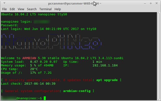
Logged Into NanoPi
If you need to power off the NanoPi, use the command “sudo shutdown now -h” and enter your password. Once the board says “Power down.” you can remove the power.
Step 2 – Installing Required Software
Software to be used :
- fswebcam – to interface with the webcam
- crontab – to schedule image updates
- ftp – an ftp client
- sshpass – tool for passing the password to other commands we’ll be using
- Optional – ImageMagick – not used here, but this is a very flexible tool that can be used to process images in a script – allows you to generate montages, scale images and much much more.
Power up and log into the NanoPi, the USB UART adapter is no longer needed, so you can plug the NanoPi in anywhere as long as it has ethernet and power. First things first, we make sure that all the software lists and software is up to date, to do this, enter the following command and then go and make a cup of tea, and perhaps have a slice of cake :
sudo apt-get update && sudo apt-get upgrade
Once the computer returns to the command prompt, we’ll install the programs that we’ll need with the following command:
sudo apt-get install fswebcam sshpass ftp
While these programs install, set up an sftp server into your webserver that you already have. Write down the server address, username and password.
Enter the following command :
sudo nano /root/script.sh
This will open a command line editor, editing a new file located in the folder /root/, called script.sh. Type, or paste in the following (ctrl-v won’t work, you’ll need to right click in the window and select paste).
fswebcam --fps 15 -r 640x480 --jpeg 85 -D 0 /home/<username>/picture.jpg -S 8
sshpass -f /root/data sftp <SFTPUserName>@<SFTPDomain> << EOT
put /home/<username>/picture.jpg ./
quit
EOT
You will need to change <username> to read the name of the username you set up on your NanoPi, SFTPUserName to the username for your SFTP server and SFTPDomain to the address of your SFTP server. Once done, press ctrl-x followed by the ‘y’ key, followed by the enter key, to exit and save your file.
Next, we store the password for your SFTP server. Storing passwords as text is never a good idea. My provider hasn’t given me a way of generating a key and so I’m a little stuck. To minimise the chance of issues, I am storing the password in a file controlled only by root, but if someone gets your root password and access to the machine, they’ll be able to read it. My machine will be behind a firewall with not external access. Suggestions for better ways of doing this are welcome.
Use the following command to store the password in the root account, in a file called “data” :
sudo echo <yourSFTPpassword> /root/data
Obviously, replace <yourSFTPpassword> with the password for your SFTP server. SFTP stands for SSH file transfer protocol – similar to regular FTP, but using an SSH to encrypt the traffic.
The script we have written takes a picture, saves it as picture.jpg, connects to our SFTP server using an encrypted connection and the password stored in the file “data”. It then uses feeds the put command into the sftp software to send picture.jpg to the remote server, specifically saving it to the current active directory. In my case this would be the top level of the domain, so the image would appear at http://elephantandchicken.co.uk/picture.jpg (which it doesn’t, because this is an example and not actually what I did).
The script we wrote currently is not executable and to make this useful we want to run the command every so often automatically. To do this, we use a built in command called crontab. Enter the following two commands :
sudo chmod +x /root/script.sh
sudo crontab -e
The first command gives permission for the file script.sh to be executed as a script. The second command opens the settings file for cron, our scheduler. The sudo at the start means that we will be running it as root, and so can run the command we created as it belongs to root. Move to the bottom of the file using the cursor keys and add a line with the following :
*/15 * * * * sudo /root/script.sh
Save and exit as before, with ctrl-x, ‘y’, and enter.
This is a bit of a rushed description and I’ll try to come back to refine / improve. I’m currently waiting on some power injector / splitter cables so I can set up the board in the shed with only a single cable (ethernet) from the house. This works well as I have some weatherproof ethernet.
Note for some cameras
When using a SQ11 type camera, I found that I was getting an error when trying to fetch a picture over USB. This was fixed by executing the following command on the command line :
echo "options uvcvideo quirks=2" >> /etc/modprobe.d/uvcvideo.conf