Economatics Smart Box
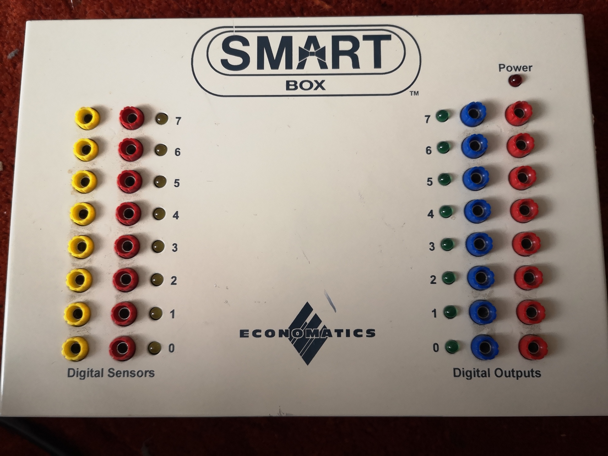
A little while ago, I bought myself a Economatics Smart Box (SB-04). My intention is to reverse engineer the serial protocol so that I can use it from a modern (Linux, but the information will be useful to others) computer. These boxes were common in schools in the UK through the 90s (and possibly before). Older variants worked with the BBC Micro. This is what they look like if anyone has forgotten or hasn’t seen one before :
A couple of minor issues so far – Number 1 – This specific model (the SB-04) doesn’t have mains in like some of the older versions, it has 12v AC in – don’t know about you, but I’ve hardly seen any AC-AC PSUs in years.
I’m aware that often you can just use a DC PSU of the same voltage with such equipment because the first thing that happens on the circuit board is that the supply is rectified and smoothed… using a DC supply just means that the supply is always going through two of the diodes and the capacitor remains permanently charged. As long as you’re within the diode ratings and the resultant voltage is close enough, there isn’t an issue. My thought was to check the circuit and see if there was any obvious reason why this wouldn’t work, which is where we get to issue Number 2…
Anti-tamper screws. I managed to get these out using a tiny socket and pushing down hard.
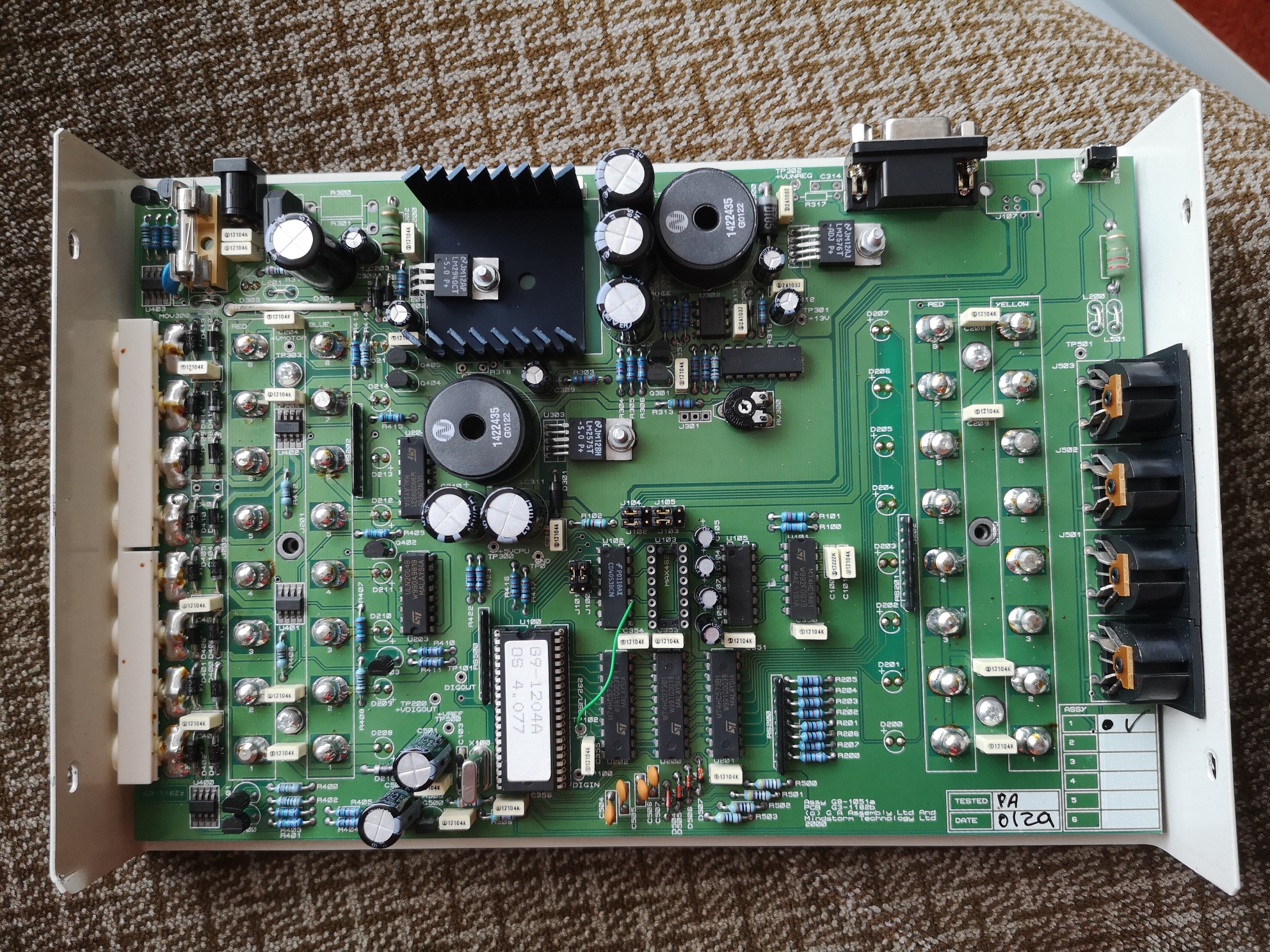
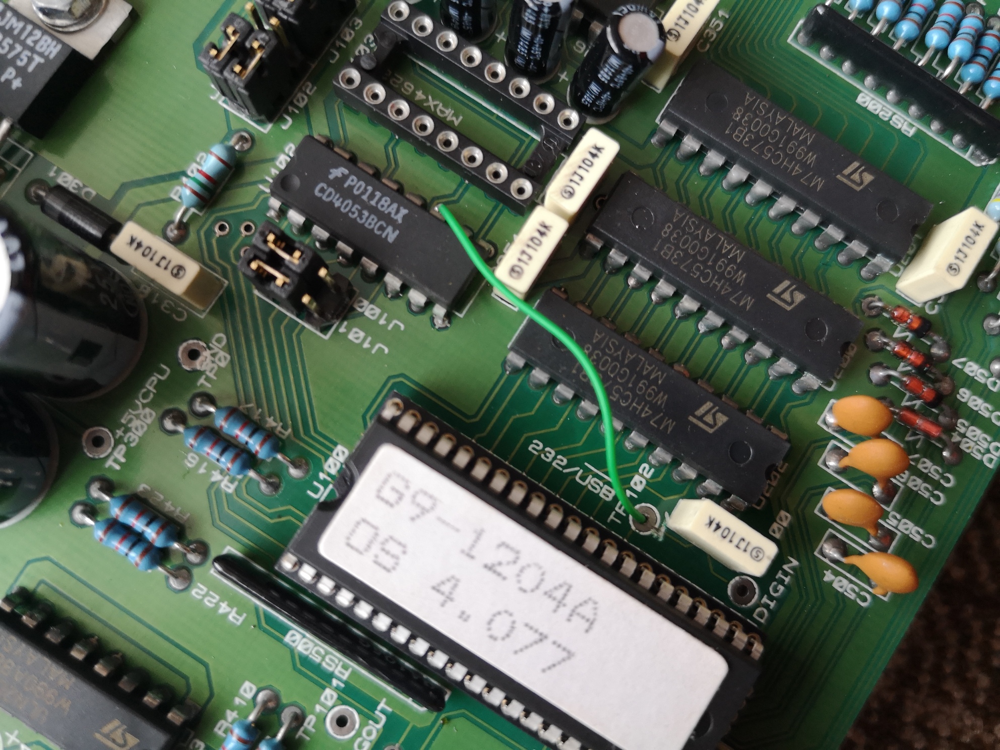
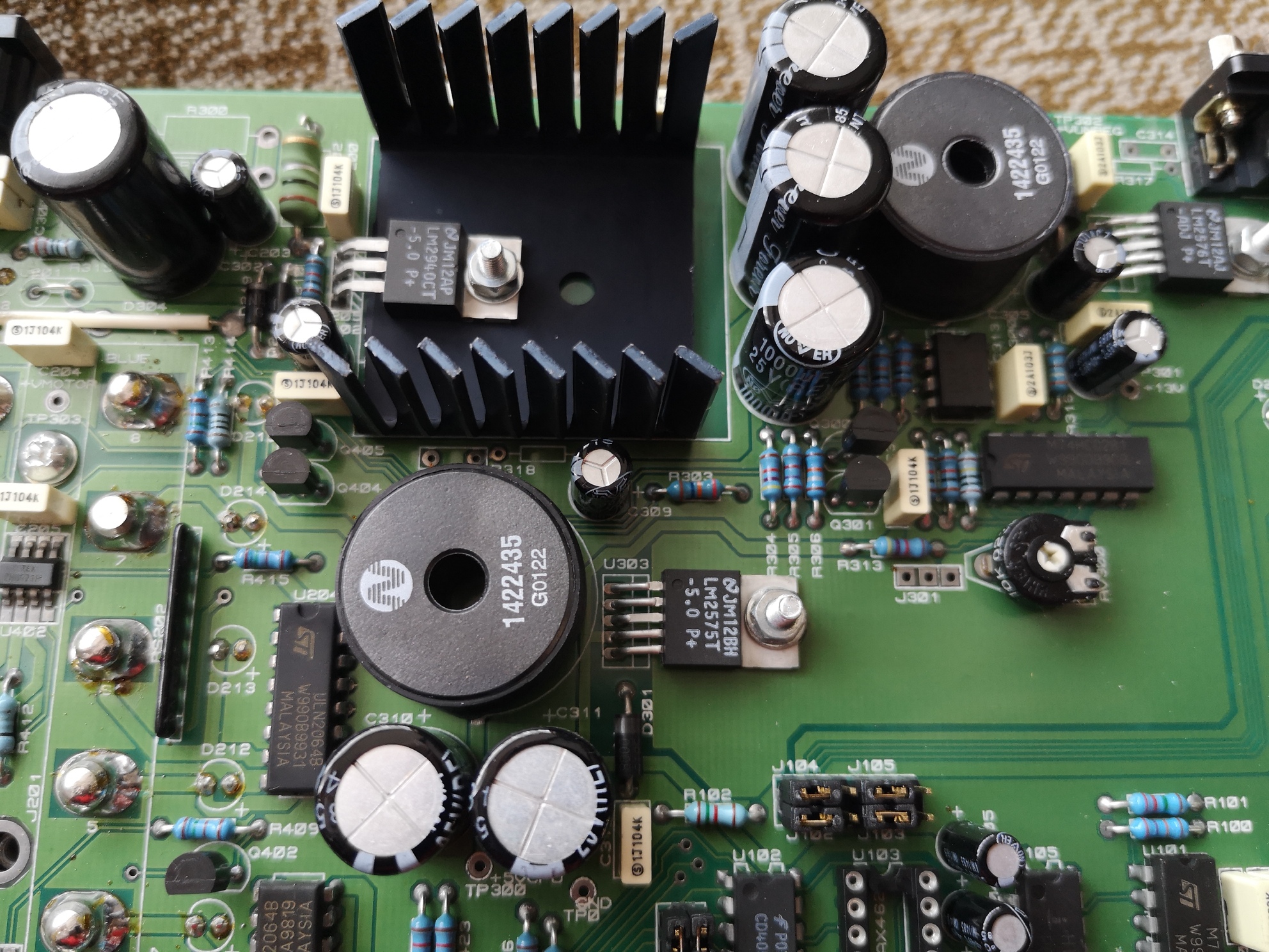
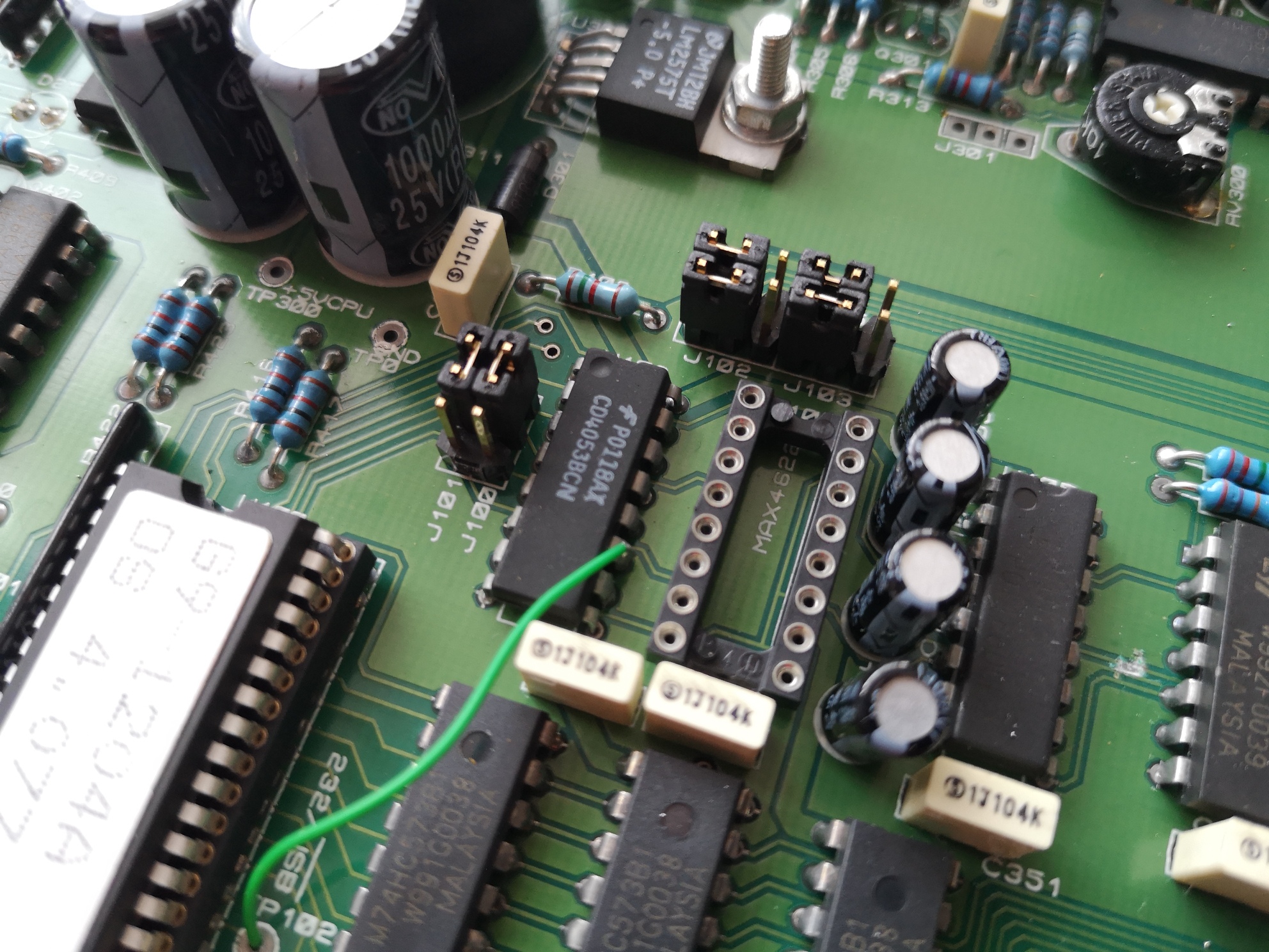
Lovely looking PCB inside designed by “G A Assembly Ltd” and “Mindstorm” (I wonder if there is any connection to the Lego Mindstorm?). Note one bodge wire, a socketed chip with the firmware version (with an unusual pitch), a missing MAX4622 chip (single pole double throw fast acting switch https://www.maximintegrated.com/en/prod … X4622.html) and space for a USB B socket. The digital outputs are buffered with ULN2064b chips (these are darlington pair arrays).
Anyway, I’ve got distracted.
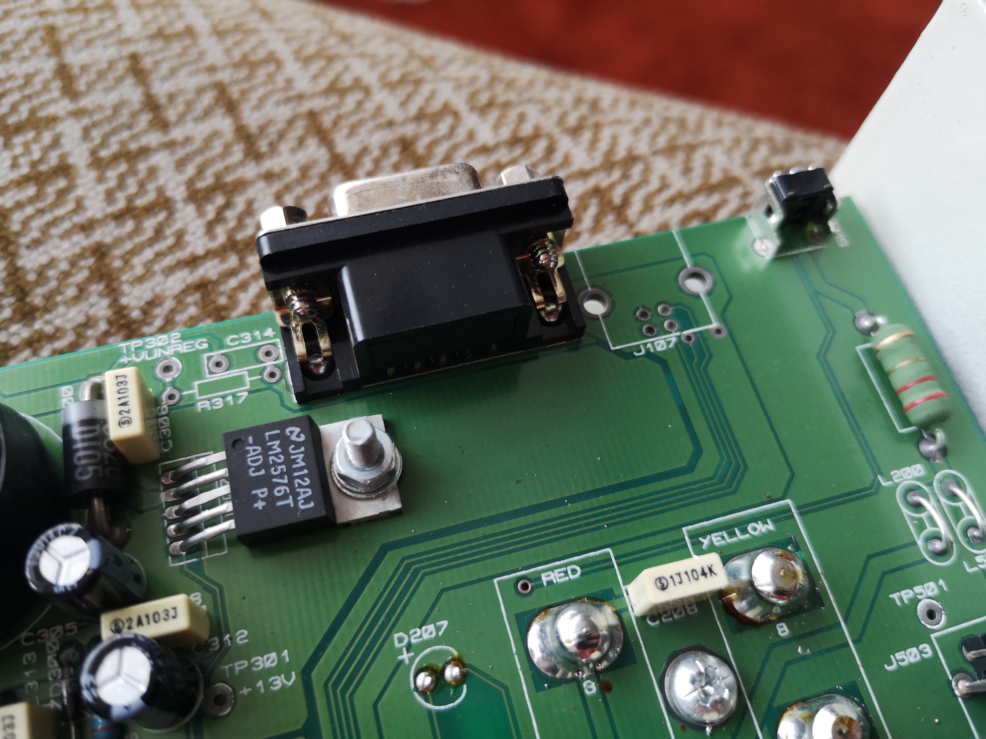
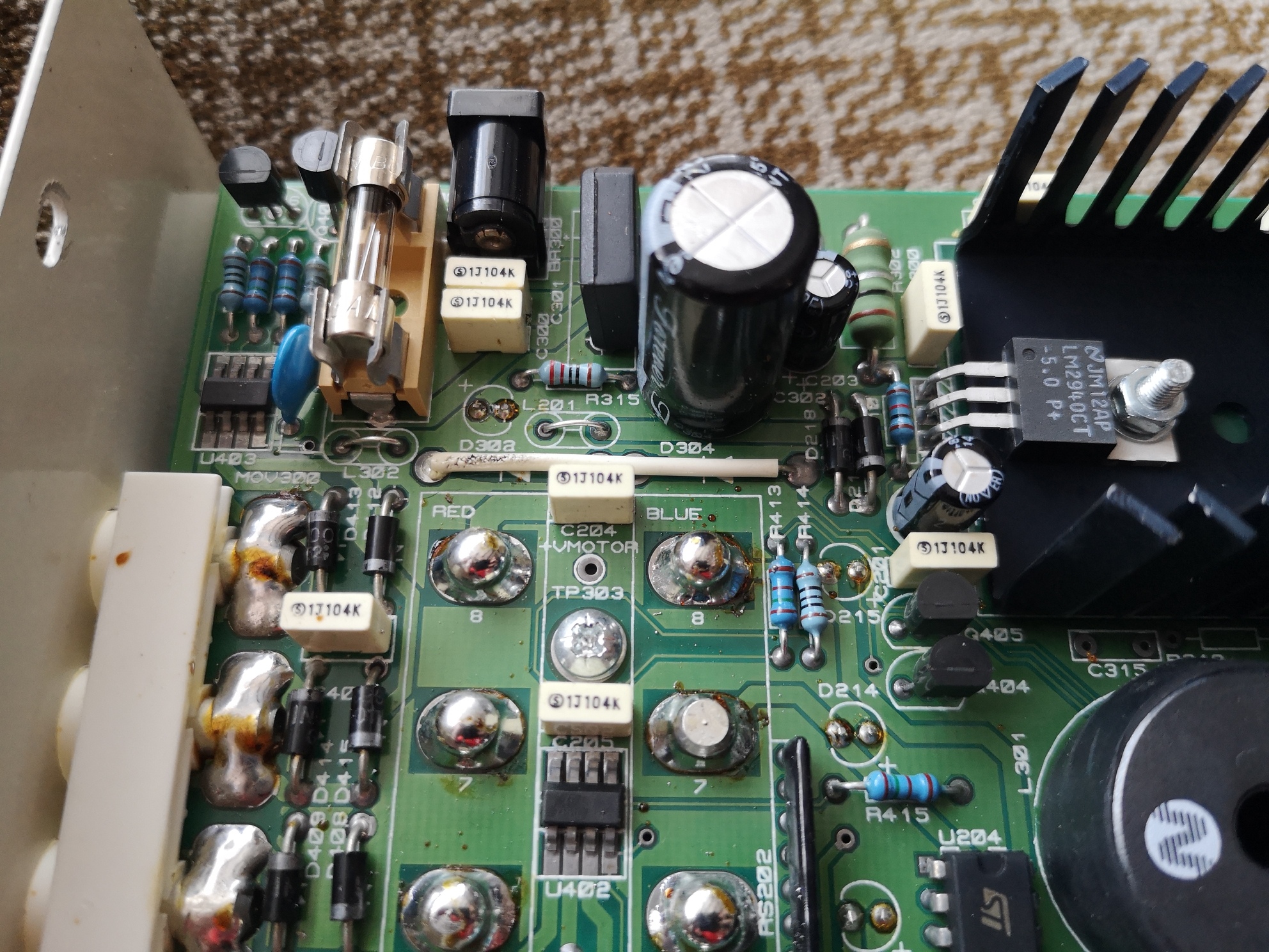
First point – there is no obvious rectifier, the PSU portion of the circuit is complex and includes two large inductors by the look of it. I’ll have to do a bit more digging and look up what some of the components are.
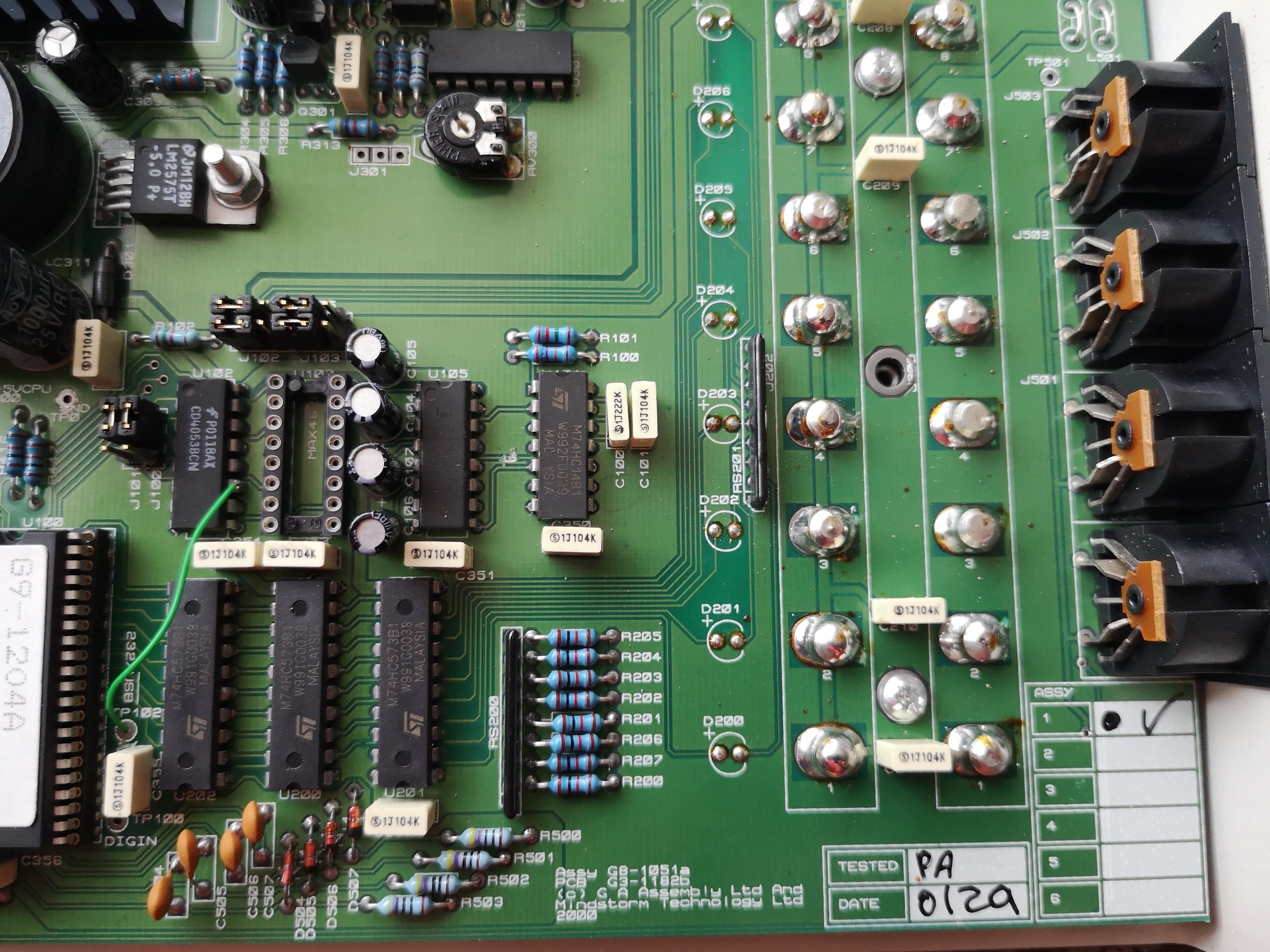
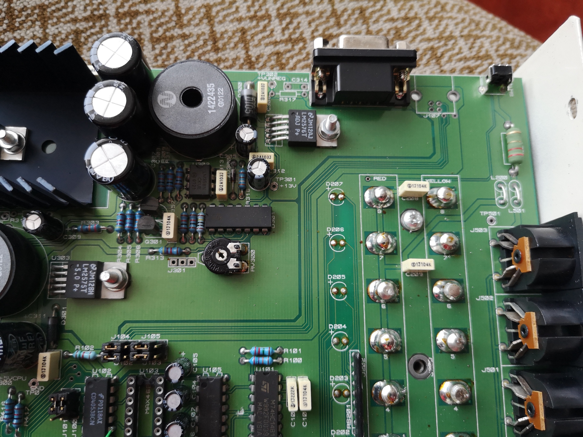
Second most important point – does anybody have a photo of the USB version of this board – I’d be interested in adding USB if I can. Current theory – the bodge wire is hardwiring my board to Serial and saving the need for the MAX4622 chip for switching between USB and RS232. There are a bank of jumpers that look interested and are next to the USB lines. I’m also wondering is the firmware the same in the USB and Serial variants?
Photos of the top side of the PCB (actually the bottom as it sits on the desk) for interest.
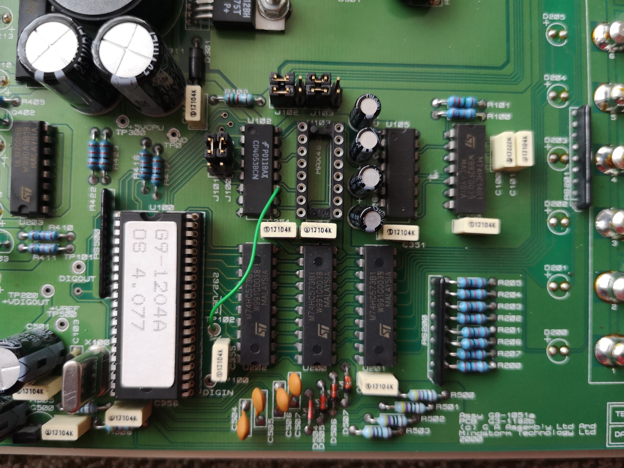
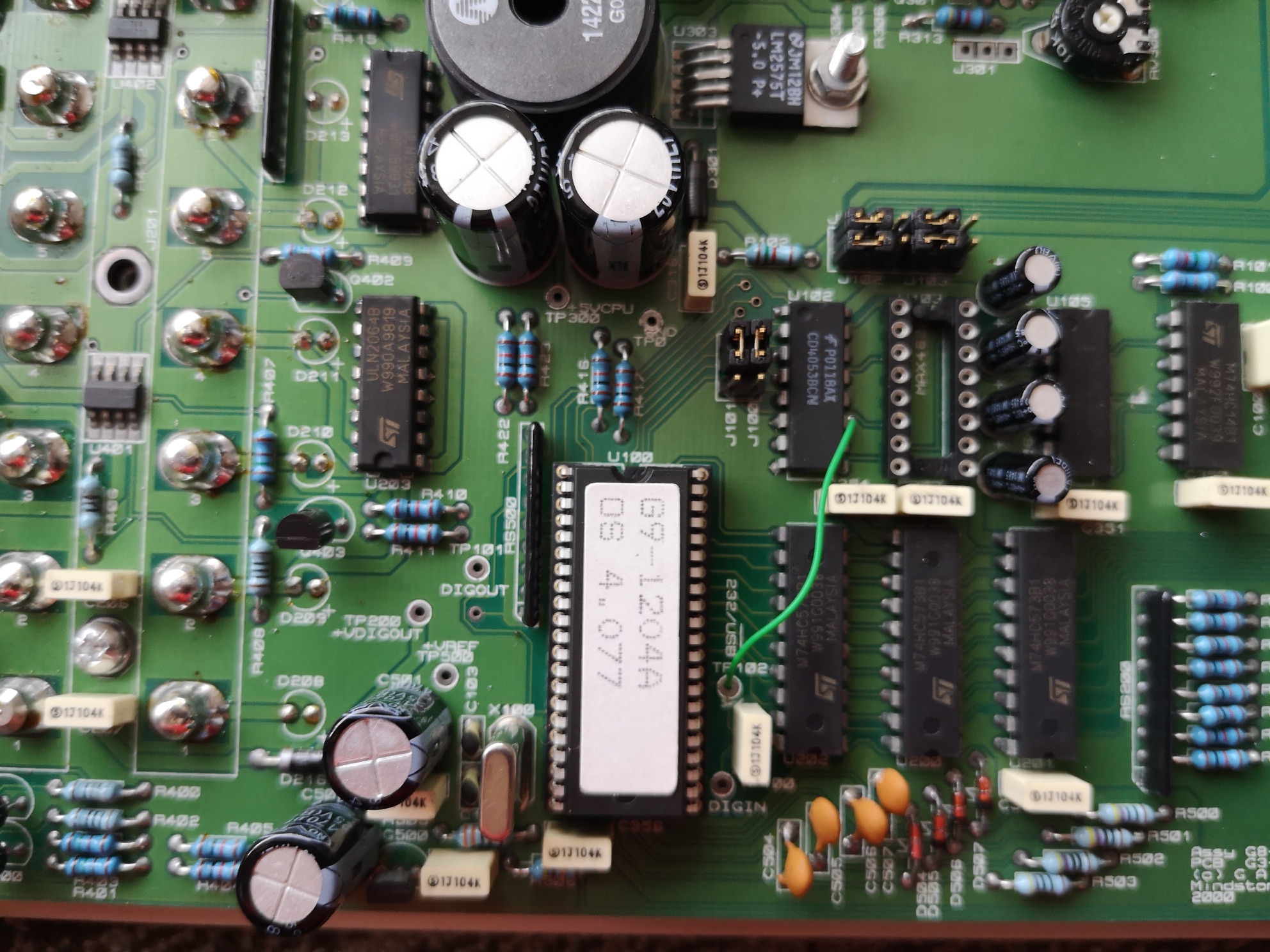
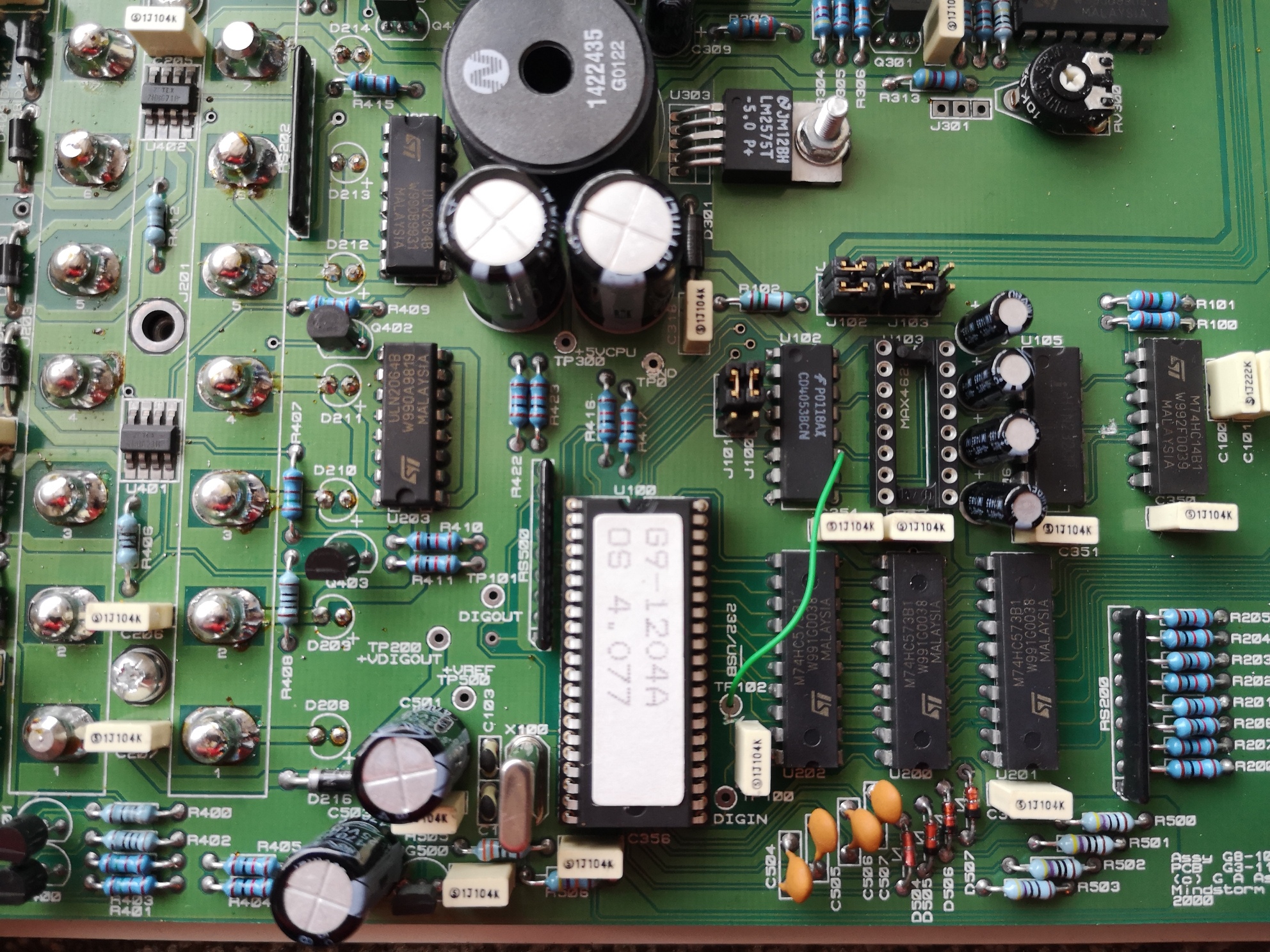
I think the main chip might be some kind of 6502 based MCU or similar – I can’t find a good datasheet online that exactly matches. It has a reduced pin pitch, 42 pins and it looks like the Crystal is connected to pins 19 and 20.
A 6502 based MCU would make sense given that the company made BBC Micro peripherals.
Older versions of the board are basically an embedded 6502 computer with RAM, ROM, an ADC and a VIA. My newer version is based on a Mitsubishi microcontroller, the M37536E8SP.
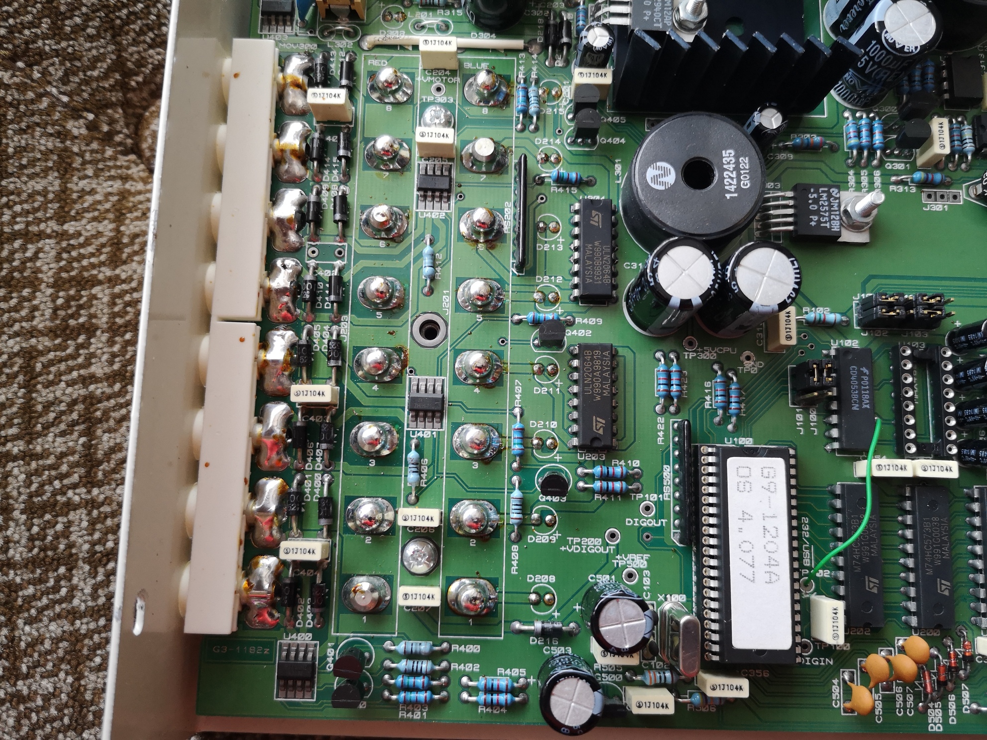
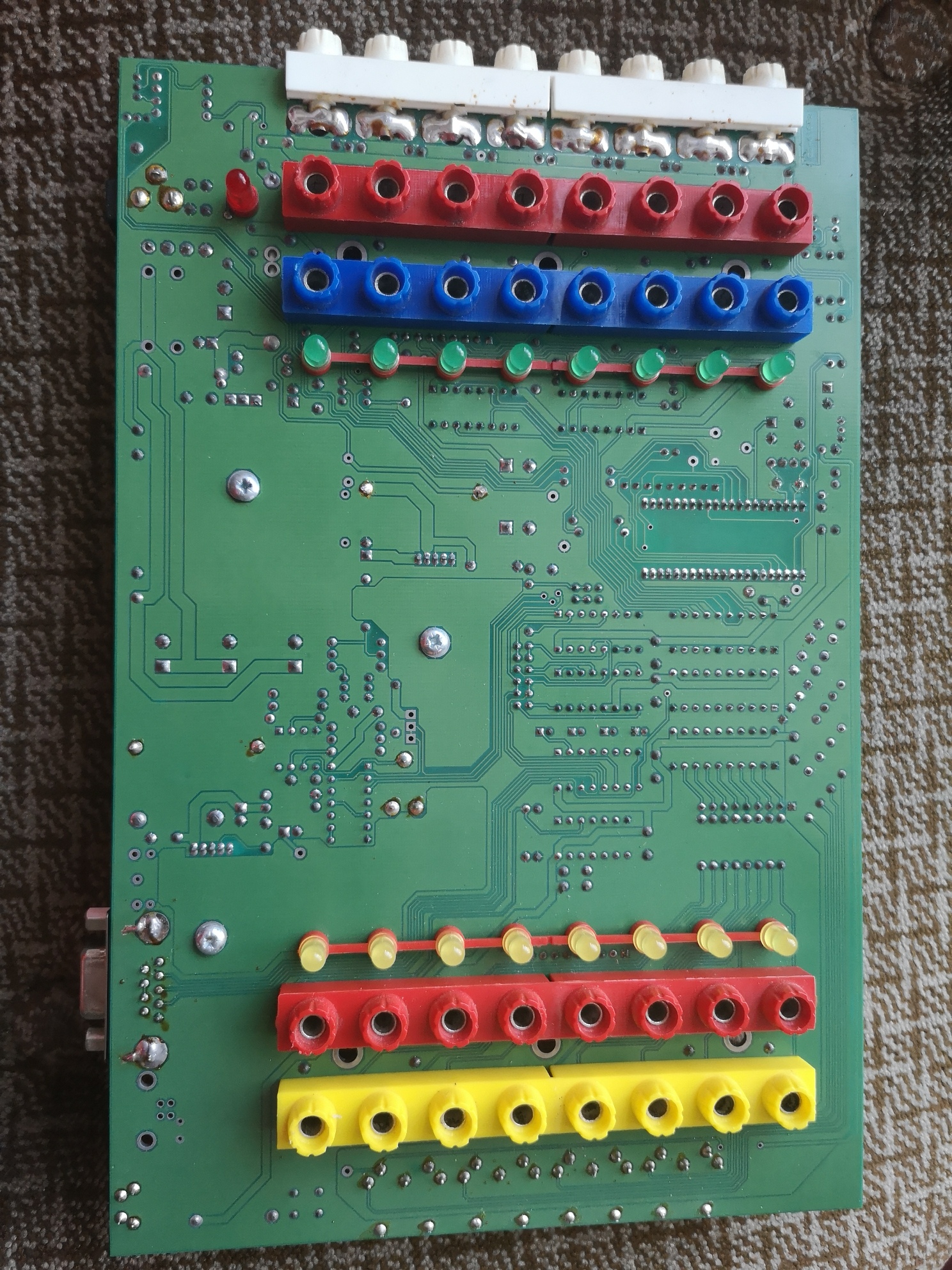
I’ve taken the board completely out of the case now. No components on the reverse, but useful for tracking traces. I’ve also noticed that there is a cut trace next to the test point that the bodge wire is attached to (separating it from a capacitor that looks like it is attached to a power rail judging by the track width – they must have accidentally tied it high).
Underside of the PCB :
Thoughts welcome, photos of the USB variant would be gratefully received!
___________________________________________________________________
Update – Some progress. I have digital write working from Python. I was lucky enough to find this page, which includes a download of sample code for controlling the Smart Box from VB6. Helpfully, this includes a number of the serial commands for making the box do various things. I’ve been able to extract the commands for the core functionality.