Writing LED sequences can be quite a faff when you’re making your own programs and hardware. I decided that a handy way of visualising the patterns would be… to visualise them, as an image. To do this, I’ve written a simple program that takes a bitmap image and outputs the colours of each pixel in each row, to the corresponding LED. The image is the same width as the target number of pixels, and each row represents a frame.
This allows me to do my LED sequencing using software I’m already familiar with, such as Photoshop or GIMP.

Cylon Eyes
So far, I’ve had versions of the program (re-written for required variations in available libraries) running on the Orange Pi (Armbian), ESP8266 (Arduino IDE) and the Raspberry Pi (twice, because I lost the original version). This post covers the latter, using the current libraries discussed on the Adafruit website, which unfortunately seem to only work with Python 3.
Required Equipment & Setup
For this tutorial, you will require the following :
- A Raspberry Pi, cables and an SD card
- A string of WS2812B LEDs – 8 is a good number
- Appropriate wires to connect the LEDs to the Raspberry Pi GPIO header
I’ve used the linked LEDs as they are convenient for testing. You will need to solder wires, or a header to these – I usually lay a standard male header (4 pins) on the pads and solder it down as it is handy for prototyping. The male header lets me use female->female dupont wires to connect to a Raspberry Pi. Also note that some variations have the red and green wired backwards – this can be easily be fixed in software (I have included a boolean near the start of the code in pictureLED.py to enable the switch).
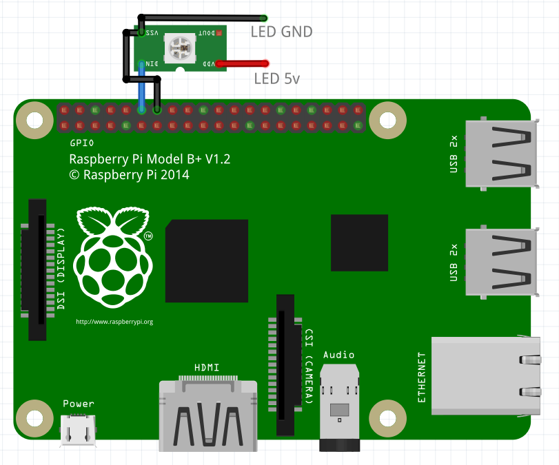
The LEDs should be wired into the Raspberry Pi while it is powered down to reduce the chance of fatal mistakes (always rewire with a computer powered down as they are very sensitive to electrical shocks and the GPIO pins are wired directly into the inner gubbins of the main chip). Wiring is as follows, where the red wire goes to +5v, the blue wire to data and the black wire to ground (there are two on the suggested LED part which is useful when using separate power supplies for the Raspberry Pi and the LEDs).
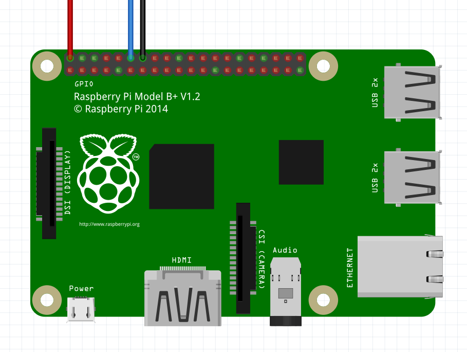
Raspberry Pi LED Wiring
The WS2812B LEDs are only borderline able to be driven from 3.3v to the data pin (the Raspberry Pi does this). While this is true, with short wires I have never had an issue. I will detail how to use a MOSFET to increase the data signal voltage to 5v later.
I will assume you have a clean install of Raspbian on the SD card in the Raspberry Pi. Before doing anything else, ensure you run the following command in a terminal :
sudo apt-get update
This updates the database of software on the Raspberry Pi and ensures that you’re requesting the latest versions of programs.
Next run the following commands in a terminal :
sudo pip3 install rpi_ws281x
sudo pip3 install adafruit-circuitpython-neopixel
The first time I ran these commands, I had an error for an unknown reason. I ran them again and everything installed properly.
First Test
To make sure everything is working, enter the following program into your favourite text editor on your Raspberry Pi and save it as test.py in a new folder (creating a new folder in the current directory : mkdir <foldername>, switch into the new folder : cd <foldername>, editor suggestion : nano test.py).
#!/usr/bin/env python3
# The line above tells the Raspberry Pi that we want to run this
#   script in Python 3 - so we don't have to tell it later

import board
import neopixel
from time import sleep

# An example program that cycles through Red, Green Blue and then stops

LEDcount = 8

pixels = neopixel.NeoPixel(board.D18, LEDcount)

#red
pixels.fill((100,0,0))
sleep(1)
#green
pixels.fill((0,100,0))
sleep(1)
#blue
pixels.fill((0,0,100))
sleep(1)

# and off
pixels.fill((0,0,0))
If you’re powering the LEDs from the Raspberry Pi, do not turn on too many. 8 is likely to already be too many as they use up to 60mA each (480mA for 8!). To limit power in these examples, I’m not using full brightness (full brightness would be 255 in the first test program), limiting the number of lit LEDs or am only using single colours at a time. For white light and full brightness on all LEDs – use an external power supply if you have more than one or two LEDs! Thanks to PJRC for actually doing some measurements.
Once entered and saved, from a terminal in the saved file’s directory, enter the following command to give the file permission to execute as a script :
chmod +x test.py
“chmod” is the permissions modification command and I think of “+x” as meaning “plus executable”.
We’re ready to run our test – with everything connected, run the following command in the terminal :
sudo ./test.py
If everything goes to play, you should see the connected LEDs cycle through red, green and then blue before turning off. If you see any errors, google is your friend. Also check that you ran the command while in the correct directory, and have permission to use the sudo command.
Make a “Clear” Script
A useful script to make at this stage is a “clear” script. This means if you interrupt another script, or create a script that leaves LEDs on and you want to get rid of them, you can run this script to tidy them up.
#!/usr/bin/env python3
import board
import neopixel
import sys

# assume a default 200 LEDs
LEDcount = 200

# handle parameter
if len(sys.argv) == 2:
   # we have been passed a parameter - this should be the number of LEDs
   LEDcount = int(sys.argv[1])

pixels = neopixel.NeoPixel(board.D18, LEDcount)

pixels.fill((0,0,0))
As before, enter the program, save it with a name (clear.py for example) and then make it executable with chmod. This script can be used in two ways – if you note the “handle parameter” if statement, by using a parameter when running the script you can define how many LEDs you would like to clear. If no parameter is passed, the script assumes you have 200. Note that overestimating is not an issue and so 200 will clear any number up to 200. If you have 201 LEDs, the final LED will remain lit!
To use the script you’ve just entered, type the following at the command line :
sudo ./clear.py
This will clear the first 200 LEDs. To clear a specific number of LEDs (for example, the first 4 of 8 LEDs or if you have 450 LEDs) :
sudo ./clear.py 4
sudo ./clear.py 450
Preparing an Image
Creating the Image we’ll be using to control the LEDs is fairly trivial if you are familiar with any painting programs. The more basic the painting software, the easier the creation! The only complication is making sure that you save in the correct file format (24bit bitmap “.bmp”). Note that I previously tested JPEGs, but found that the compression made black not equal 0,0,0 and so LEDs would be visibly lit when I didn’t want them to be.
For demonstration, I will use GIMP to create my image, because it is free.
- Launch GIMP and create a new image. Make it as wide in pixels as the number of LEDs you have connected (8 for me) and as tall as the number of frames you’d like (16 for me).
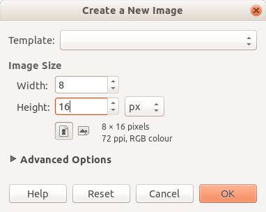
New Image
- Fill the drawing area with black (RGB 0,0,0).
- Zoom in lots until you can see individual pixels and start painting. The pencil (individual pixel drawing tool) is probably best for this. In GIMP you need to change the pencil “brush” size to 1px.
- Draw your picture.
- Once done, to save in GIMP, select “Export As…” from the File menu.
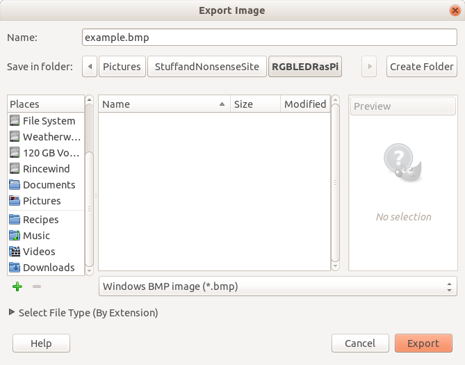
Export Image
- Name your file, pick a location, select “Windows BMP image” and click Export.
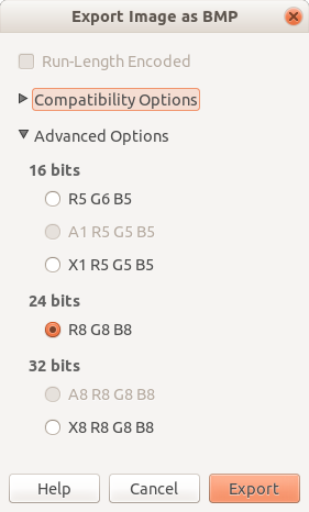
Export Options
- Select “24 bits” under “Advanced Options” in the Export Image as BMP dialog box which appears.
I have created the following example.bmp. Note the red graduated tint in the lower half (only between 0 and 80 out of 255 intensity, which will be significantly more pronounced on the LEDs). I have uploaded the actual file (the following image has been enlarged to make it visible) and it can be downloaded from here (right click and select “Save link as…”).

Example
If you have drawn your image on a computer other than your Raspberry Pi, you will want to transfer it. There are many ways of doing this, from USB drive, to email. I will be using a built in tool command line tool available on Linux and MacOS called “scp”.
In this example, we are assuming that the image file is saved in a folder called “To Transfer” in your home folder on your desktop / laptop computer (aka “the source”), is called “example.bmp”, that the network name of your Raspberry Pi (aka “the destination”) is still the default “raspberrypi”, the username is the default “pi” and that you want to move it to a folder in the Raspberry Pi home directory called “RGBLED”.
If you haven’t consciously changed the network name from “raspberrypi”, it will still be this – if you have, use the new name instead. You can see the network name in the command prompt on the Raspberry Pi if I remember correctly, it is the bit after the “@” symbol).
To move the file from the source to the destination, enter the following command on the source computer :
scp ~/To\ Transfer/example.bmp pi@raspberrypi.local:~/RGBLED/
You will be asked for your Raspberry Pi password (the destination, not the source) and you should almost instantly see the file as 100% sent and the source returns to the standard command prompt. If there is an error, make sure that the source and destination are on the same network, the file paths are correct at both ends, the password is correct and that you haven’t made any typos. If you still have issues, there are websites available that will take you through the process more carefully if you search for “transferring files to a Raspberry Pi using scp”.
In later examples, I will assume that the file “example.bmp” is located in the ~/RGBLED/ (also known as /home/pi/RGBLED/) folder on the Raspberry Pi.
The pictureLED.py Script
The main python script which converts an image into a sequence of LED based patterns is as follows, or can be downloaded directly from here (right click and select “Save link as…”). I recommend placing it in the same “~/RGBLED/” folder on the Raspberry Pi.
#!/usr/bin/env python3

#******************
#* pictureLED.py - convert bmp image into LED sequence Code
#* https://elephantandchicken.co.uk/stuffandnonsense
#* Circuit :
#* Connect LED ground to both the Raspberry Pi ground and the LED power supply's ground
#* Connect LED data to pin D18 (if not boosting with MOSFET)
#* Connect LED +V to the LED power supply 5V
#* Do not mix 5V and 3.3V!
#* If in doubt, details of the circuit and software for controlling from linux
#* are on my website
#*******************

import sys
import board
import neopixel
from PIL import Image

from time import sleep

# Edit the following line if red and green are backwards
switchColours = false

def fixColour(colour, scale):
    # correct the colour order for my ws2812 LEDs and scale the brightness
    # correct colour by switching [0], [1] and [2]
    theResult = (int(scale*colour[0]/100),int(scale*colour[1]/100),int(scale*colour[2]/100))
    if switchColours:
        theResult = (int(scale*colour[1]/100),int(scale*colour[0]/100),int(scale*colour[2]/100))
    return theResult

if len(sys.argv) == 1:
    print("You've not provided any details! Command format is <required> [option] : sudo pictureLED.py <image.bmp> [fps] [loop? 1/0] [loopdelay] [brightness percent] [pin]")
    quit()
if len(sys.argv) > 1:
    # identify image file - use defaults for all other parameters
    imgfile = sys.argv[1]
    fps = 15.0
    maxIntensity = 100
    pin = 18
    loopimg = True
    loopDelay = 0
if len(sys.argv) > 2:
    # set the fps
    fps = float(sys.argv[2])
if len(sys.argv) > 3:
    # loop?
    if sys.argv[3] == "1":
        loopimg = True
    else:
        loopimg = False
if len(sys.argv) > 4:
    # loop delay (at the end of each cycle)
    loopDelay = float(sys.argv[4])
if len(sys.argv) > 5:
    # set a maximum LED intensity and scale all values
    maxIntensity = int(sys.argv[5])
if len(sys.argv) > 6:
    # parameter 5 - set pin for neopixel data
    pin = sys.argv[6]
im = Image.open(imgfile)
pix = im.load()
pixw = im.size[0]
pixh = im.size[1]
print("Image size = ",im.size)
PIXEL_NUM = pixw

if pin==18:
    pinName = board.D18
    # add other options here
else:
    pinName = board.D18

pixels = neopixel.NeoPixel(pinName, PIXEL_NUM, auto_write=False) # pin, number of LEDs

stat = True

while(stat):
    for y in range(0, pixh):
        for x in range(0, pixw):
            pixels[x] = fixColor([pix[x,y][1],pix[x,y][0],pix[x,y][2]],maxIntensity)
        pixels.show()
        sleep(1/(fps))
    sleep(loopDelay)
    stat = loopimg
pixels.fill((0,0,0))
pixels.show()
The program is not actually that large, with the majority of it being a clumsy decoding of the various parameters sent by the user when they execute the command. For a fixed application, much of this could be removed to produce something like the following (untested) code :
#!/usr/bin/env python3

#******************
#* fixedPictureLED.py - convert bmp image into LED sequence Code
#* https://elephantandchicken.co.uk/stuffandnonsense
#* Circuit :
#* Connect LED ground to both the Raspberry Pi ground and the LED power supply's ground
#* Connect LED data to pin D18 (if not boosting with MOSFET)
#* Connect LED +V to the LED power supply 5V
#* Do not mix 5V and 3.3V!
#* If in doubt, details of the circuit and software for controlling from linux
#* are on my website
#*******************

import sys
import board
import neopixel
from PIL import Image

from time import sleep

#################
# Define the image path here!
imgfile = "/path/to/the/image.bmp"
#################

# Other parameters :
fps = 15.0
maxIntensity = 100
pin = 18
loopimg = True
loopDelay = 0
switchColours = false

def fixColour(colour, scale):
    # correct the colour order for my ws2812 LEDs and scale the brightness
    # correct colour by switching [0], [1] and [2]
    theResult = (int(scale*colour[0]/100),int(scale*colour[1]/100),int(scale*colour[2]/100))
    if switchColours:
        theResult = (int(scale*colour[0]/100),int(scale*colour[1]/100),int(scale*colour[2]/100))
    return theResult

im = Image.open(imgfile)
pix = im.load()
pixw = im.size[0]
pixh = im.size[1]
print("Image size = ",im.size)
PIXEL_NUM = pixw

if pin==18:
    pinName = board.D18
    # add other options here
else:
    pinName = board.D18

pixels = neopixel.NeoPixel(pinName, PIXEL_NUM, auto_write=False) # pin, number of LEDs

stat = True

while(stat):
    for y in range(0, pixh):
        for x in range(0, pixw):
            pixels[x] = fixColor([pix[x,y][1],pix[x,y][0],pix[x,y][2]],maxIntensity)
        pixels.show()
        sleep(1/(fps))
    sleep(loopDelay)
    stat = loopimg
pixels.fill((0,0,0))
pixels.show()
Note the “auto_write=False” parameter passed when generating the “pixels” object. This changes the library’s behaviour so that it only sends updates to the LEDs once the function “pixels.show()” is called.
As before, once you have pictureLED.py saved (pictureLED.py specifically as fixedPictureLED.py is just an example application) on the Raspberry Pi, run the chmod command to allow the file to be executed.
Running the pictureLED.py Script
To run pictureLED.py, open a terminal with the current directory matching the location of both pictureLED.py and example.bmp. The command format is as follows :
sudo ./pictureLED.py <filename.bmp> [fps] [loop? 1/0] [loopdelay] [brightness percent] [pin]
Parameters between “<>” are required and parameters between “[]” are optional, although all preceding optional parameters are required. These are two example commands :
sudo ./pictureLED.py example.bmp
sudo ./pictureLED.py example.bmp 2 0 0 50
The first example uses all default settings (15 fps, loop, zero second loop delay (time before the pattern repeats), 0% brightness reduction and the default pin) on the image “example.bmp”. The pattern will repeat indefinitely – to stop it, press Ctrl-c.
The second example passes a number of parameters, more specifically describing how we want the program to run. In this example, we run at 2 fps, not looping, zero second loop delay, at 50% of full brightness. Note we do not specify the pin – this is because pin D18 is currently the only available pin in my code.
Running at Boot
A simple way to make your LED sequence run when the Raspberry Pi powers on (note, powers on, not when you log in) is to edit the operating system file “/etc/rc.local”. Absolute care should be taken, as if you make a mistake, the Raspberry Pi will not finish booting. Assuming that the absolute path (from the root level of the disk, not from the Home (aka “~”) folder) for pictureLED.py is “/home/pi/RGBLED/pictureLED.py”, enter the following command in a terminal :
sudo nano /etc/rc.local
A file will open in the text editor nano. Use the arrow keys to scroll to the bottom of the file. The last line should be “exit 0”. Above this enter the following new text :
/home/pi/RGBLED/pictureLED.py /home/pi/RGBLED/example.bmp 2 &
There are a number of things to note here.
- All paths have to be absolute as this means that they are always correct, no matter where the current directory is when the script executes.
- “sudo” is not needed because the parent script is already executing with root permissions.
- As shown it is best (don’t not do it) to include a ” &” (that is a space followed by an ampersand). This tells the computer to run the script as a background process and means that if your script throws and error, or stops to wait for user input, the computer does not hang but keeps booting. It also means that the computer doesn’t wait for your script to finish before continuing (imagine we used the default “loop” option).
External Power Supply
To drive more LEDs at full brightness, connect the LEDs to an external 5v power supply, remembering to connect the ground between both the LED power supply and the Raspberry Pi (not doing so can damage the Raspberry Pi or LEDs as connecting the grounds holds both devices to the same reference point and avoids the voltages floating between the two supplies, potentially causing high voltages where there shouldn’t be). The following shows a suggested wiring :
External Power LED Wiring
Do not connect the 5V to the Raspberry Pi (unless you know what you are doing, and it is the only power supply to the Raspberry Pi (i.e. there is no micro USB connected)).
Remember that each LED could draw up to 60mA and ensure that your selected LED power supply is able to provide sufficient current to power all of your LEDs. Given that the supply is at 5v, this means you are looking for 5×0.06 = 0.3 watts per LED. For example, if you had 100 LEDs, you would need a power supply rated to at least 30 watts at 5v.
5v Data Signal
Another potential issue which has not impacted me, is due to the Raspberry Pi sending data to the LEDs at 3.3v. I believe that the minimum voltage required by the LEDs when running at 5v is 3v and 3.3v does not give much overhead. This is likely to result in issues when longer wires result in a further reduction in voltage, potentially causing intermittent issues or complete failure to operate.
This can be solved by voltage shifting the Raspberry Pi output using a MOSFET. The following method is actually a way of getting bi-directional level shifting (very useful for I2C), but is simple enough that we might as well use it here. I’ve based the circuit on the one here : http://www.hobbytronics.co.uk/mosfet-voltage-level-converter, please double check that my implementation is correct! Note the strip board could be smaller in reality (you could manage a 4×3!), but I couldn’t get Fritzing to show stood up resistors.
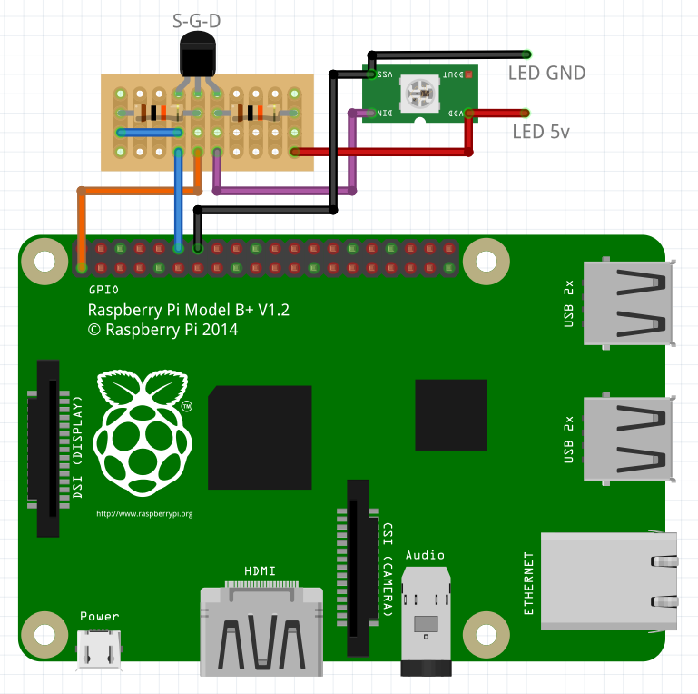
MOSFET LED Wiring
Note that the orange wire is connected to a 3.3v pin on the Raspberry Pi. As labelled, the pinout for the 2N7000 MOSFET is Source, Gate, Drain from left to right, with the flat on the package facing you.
Future Project
The next thing I’d like to do is write a program to allow me to draw animations for an n by n LED matrix and save them in this image format. It shouldn’t be too difficult and would be fun and interesting. I don’t have a significant sized LED matrix though – I think the biggest I have is only an 8×8.