I recently purchased a Atmel ATmega128 breaout board designed by LogiFind, called the ReadyAVR-64. The company seems to be imitating Mikroelektronika with their naming conventions and produce intermediately priced educational boards. They provide some examples and software, oriented around Windows as a host platform for most of their boards. I have a couple of examples for there wares, from the giant “EasyAVR128” to the more basic “ReadyAVR-28” (which I plan to swap a ATmega328 into – they do a board with one pre-installed, but it costs more). Currently, the documentation download link on their website for their ReadyAVR-64 board seems to be broken.
Despite being a blue PCB in all adverts etc. the board I received in the post was green. I had some minor postage issues, with my package been returned to sender for an unknown reason, but the seller was very honest and quick responding and the item arrived by airmail a few days after I reported my concerns.
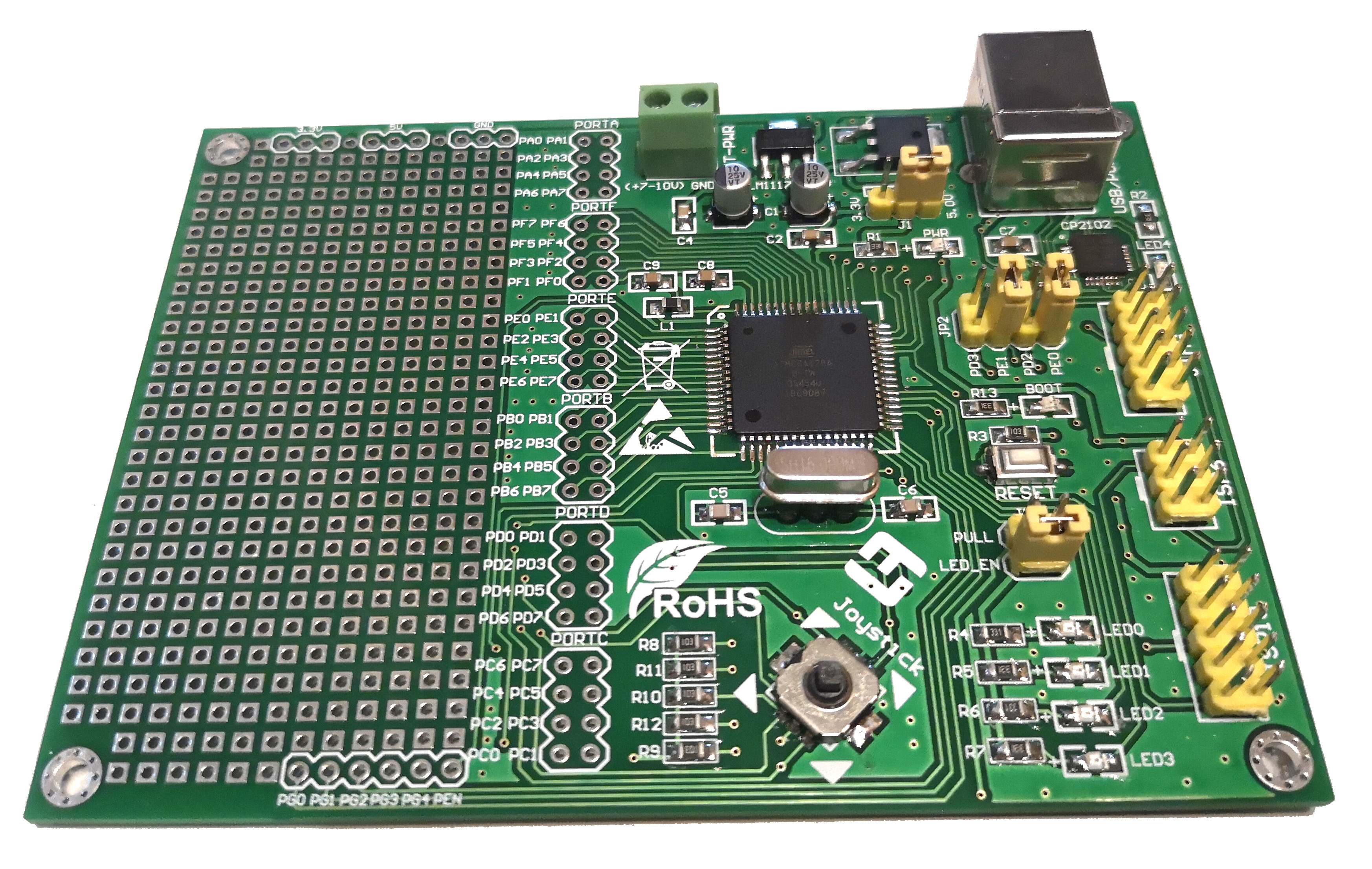
ReadyAVR-64
Upon getting my board in the post, the first thing I did was swap out the crystal oscillator for a turned pin socket. There are two reasons for this – firstly the pre-installed crystal was an odd speed (7.3728mhz – I prefer 16mhz), and secondly, a socket means I can change the speed as I wish. Making this change requires your usual component desoldering – I used some flux, an iron and some solderwick – once the crystal was out of the board I finished clearing the holes with a solder sucker. Break off a 3 long piece of turned pin female header and solder it in. You don’t even need to remove the middle pin as there is an unconnected hole already on the PCB.
The next thing I did was replace the pre-installed bootloader with a variant of optiboot. I can’t remember exactly where I got it, but the hex file is here. This USB bootloader uses the PE1, PE0 serial port and so I had to switch the jumpers on JP2 for it to work. Loading in the new bootloader is done through the ISP6 or ISP10 ports. I used my STK500 with AVRdude, as I’ve had some difficulties programming AVR128s with my usbasp in the past. It should be possible to follow “Arduino as ISP” instructions to reflash the board. I wont go into depth here. At some point I’ll write a guide to reflashing bootloaders onto AVRs, but there are already a lot of guides out there. For reference, I used the following two AVRdude commands to setup the bootloader and fuses on my board :
avrdude -p m128 -c STK500 -P /dev/ttyUSB0 -u -U flash:w:optiboot_atmega128.hex
avrdude -c STK500 -p m128 -P /dev/ttyUSB0 -U lfuse:w:0xff:m -U hfuse:w:0xc6:m -U efuse:w:0xff:m
At this point, if you wish to program the board using the Arduino IDE, you will need to install MegaCore. This adds extra microcontrollers, including the ATmega128 to the boards menu in the Arduino IDE. Installation is described in the “How to Install” section of the linked github page.
As I couldn’t find any documentation on the board due to the broken download link, I experimented and followed traces on the board until I worked out the following. Note that the LEDs are Active Low (setting the connected pin on the microcontroller to High turns them off).
- LED0 = Arduino Pin 28 (PC0)
- LED1 = Arduino Pin 29 (PC1)
- LED2 = Arduino Pin 30 (PC2)
- LED3 = Arduino Pin 31 (PC3)
- BOOT = Arduino Pin 37 (PA7)
The Joystick is connected to Port B, but required the chip’s internal pullups to be enabled before it works correctly. One way this can be done in the Arduino IDE is by using digitalWrite to set the pin HIGH after having set it to be an input. Connections are as follows :
- Joystick Up = Arduino Pin 9 (PB1)
- Joystick Down = Arduino Pin 11 (PB3)
- Joystick Left = Arduino Pin 10 (PB2)
- Joystick Right = Arduino Pin 8 (PB0)
- Joystick Click = Arduino Pin 12 (PB4)
Note that when you trigger two options at once, say for up and right, or left and click, all 5 pins trigger. The joystick connections are also Active Low, meaning the input goes low when the joystick is triggered.
The following Arduino example shows the functionality of both the LEDs and the joystick.
int LEDS[] = {28,29,30,31,37};
int Inputs[] = {8,9,10,11,12};

void setup() {
  for(int x = 0; x<5; x++){
    pinMode(LEDS[x], OUTPUT);
    digitalWrite(LEDS[x], HIGH);
  }
  for(int x = 0; x<5; x++){
    pinMode(Inputs[x], INPUT);
    digitalWrite(Inputs[x], HIGH); // enable pullup
  }

  int LED = 0;
  while(LED<5){
    pinMode(LEDS[LED%5], OUTPUT);
    digitalWrite(LEDS[LED%5], LOW);
    delay(250);
    digitalWrite(LEDS[LED%5], HIGH);
    delay(250);

    LED++;
  }
}

void loop() {
  for(int x = 0; x<5; x++){
    if(digitalRead(Inputs[x])==LOW){
      digitalWrite(LEDS[x], LOW);
    }else{
      digitalWrite(LEDS[x], HIGH);
    }
  }
}