Cheap “Arduino” on a Breadboard – Draft
Note – This is a draft version of this post. I need to take some photos and perhaps adjust the contents. I’ve also not proofread the text yet.
TL;DR
This post got a bit excessively long as I tried to include a bit of detail around the instructions. I probably should have kept it short and to the point. To overcompensate, here is a unhelpfully concise version of the instructions :
- Add “https://mcudude.github.io/MiniCore/package_MCUdude_MiniCore_index.json” to the “Additional Boards Manager URLs” field in the Arduino IDE preferences (a comma is required between each URL.
- Install MiniCore within Tools>Board>Boards Manager
- Place Chip in development board, connect USBasp to development board, plug USBasp into computer
- Select ATmega8, select 8MHz internal, select USBasp
- Click Burn Bootloader
- Load your sketch, select Sketch>Upload Using Programmer
- Done
Introduction
Often, if you’re interested in adding a small amount of intelligence to something your building or modifying, the resources of a full blown Arduino are overkill. A great way of getting the many of the benefits of the Arduino ecosystem in a cut down package and at a lower cost is to use a standalone AVR chip similar to the one found in an Arduino Uno. The following instructions discuss using an ATmega8A chip, in the DIP 28 package, although the process is very similar for other AVR microcontroller (MCU) chips. I like the ATmega8A because while it has only 1/4 of the program memory of the ATmega328P found in most Arduino Unos and many other Arduino variants, it can be purchased for less than 60p in small (x10) quantities.
Instructions to this end are reasonably readily available on the Internet already, but I’ve recently bought some parts for my dad and so wanted to pull a guide together, specifically for the things I know he is using.
Hardware we will be using :
- An ATmega8A chip (28 pin DIP)
- An USBasp in circuit programmer (ICP)
- A programmer / development board with a convenient ZIF (Zero Insertion Force) socket
Only the ATmega8A is actually required, as on the assumption you have another Arduino available, you can program the chip from another Arduino in a breadboard. How to do this is covered elsewhere in detail.
Software we will be using :
MCUDude has produced a number of useful additions to the Arduino IDE which allow you to easily program a large number of stand-alone AVR MCUs. These can be found here.
The ATMega8A
<picture>
The ATmega8A uses the same core as the ATmega328, but has a reduced feature set, including fewer PWM outputs, less RAM, less EEPROM and less flash memory for programs. Here are the basic specifications :
- Maximum speed 16MHz (with external crystal)
- 8KB flash memory for programs
- 1KB SRAM
- 0.5KB EEPROM
While the chip can use an external crystal oscillator of up to 16MHz to control its speed, it (and other AVRs) also include an internal RC (Resistor Capacitor) oscillator, which can be used to run the chip at 8MHz with no external components. Using the chip in this mode allows for very streamlined operation as you can run your software on the chip and not need a single external component other than the wires providing power… although a MCU circuit with no external components or connections might not be very exciting, or much use at all. What it does mean is that you only need to add what you want.
While 8MHz is half the speed of a standard Arduino Uno, it is still amazingly fast (on an AVR it is approximately 8,000,000 processor level operations per second). More than enough for many projects.
The USBasp
<picture>
This programmer can be bought for not much money from ebay and seems to work perfectly well for almost all of my needs. The only time I’ve needed anything more comprehensive was to recover “bricked” chips, where fusebits (low level settings on the chips which define things such as operating speed or programming method) have been incorrectly set etc. Note : never throw out a chip that wont work unless you saw the magic smoke leave it – I’ve not once irreparably damaged an AVR chip no matter how hard I’ve (accidentally) tried.
If you’re feeling up to the challenge, you can even make your own, with some guidance available at this website, which I assume to be the original developer’s site. Making your own is especially relevant as they can be made using the ATmega8 we’re working with.
This programmer differs from using the USB port directly, or using an FTDI (or similar) USB to UART serial board to program an AVR MCU / Arduino in that it directly programs the chip without the need for any software to be already running on the chip. Part of the Arduino ecosystem is the use of a small program called a “bootloader”. This program runs when the chip is first powered on or reset and looks to the serial port for communications indicating that it should start reprogramming the remainder of the chip with a new program being fed in over serial. When a new chip arrives from the factory, it does not come pre-loaded with this bootloader and so another method (an in circuit programmer) is required to load in programs, or even a bootloader. Most ISPs use the SPI pins on the AVR MCU.
ATmega8, 48, 88 Development Board
<picture>
SOME ASSEMBLY REQUIRED. This board should also program the ATmega168 and ATmega328 – I’m not certain why they haven’t included these in the ebay listing. The board is nothing special, but is useful because of a number of features.
- The ZIF socket reduces the chance of damaging the chip or board
- You don’t need to count pins working out where to plug in each wire from the programmer – the programmer plugs right in
- The circuit includes a crystal oscillator, which makes the first programming easier
- It is cheap and already exists!
Setting up the Software
Install the Arduino IDE if you don’t already have it installed. This is done by going to the Arduino website software download section and following instructions for your platform. Once you have installed the Arduino IDE, check it runs by launching it. If possible, confirm it functions with a regular Arduino board by loading the “blink” example into a board. If you are unsure how to do this, the getting started part of the official website may be useful.
Once you’re up and running, navigate to the “Preferences” dialog box through the “File” menu. You will be faced with something similar to the following :
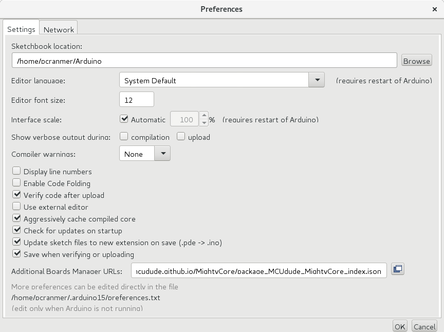
Arduino Preferences
Note the “Additional Boards Manager URLs” edit field. In a fresh install this will be empty. Paste the URL between the following quotes (exclusive) into the field : “https://mcudude.github.io/MiniCore/package_MCUdude_MiniCore_index.json”. If there is already something in the field, find the end and add a comma before pasting in the quoted URL. Close the Preferences dialog box by clicking the “OK” button.
Select the “Boards Manager” from the “Tools”>”Board” menu. The “Board” sub-menu may have the name of the currently selected board in its name just to make it impossible for me to be specific. There may be a flurry of activity while the software checks for updates to the available boards etc. Once it has finished, it is possible to search for specific boards. For some reason it doesn’t seem possible to search for the collection name, which would be sensible.
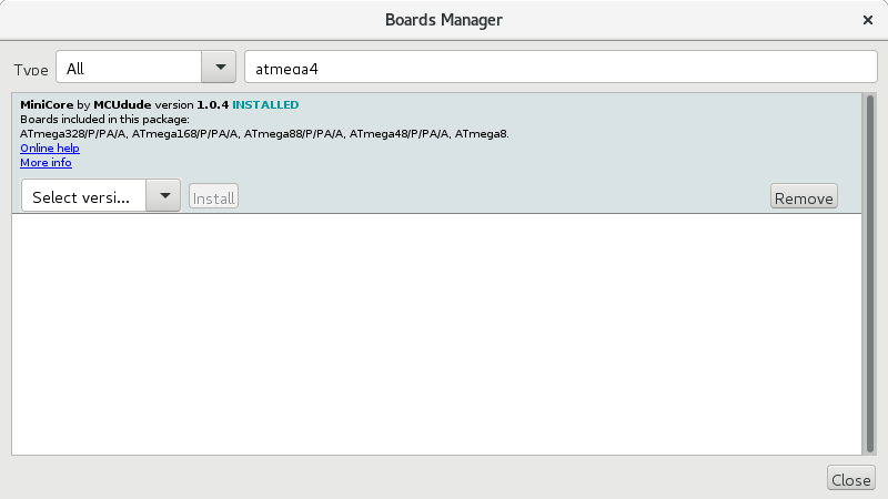
Boards Manager
In the example image above I have searched for “atmega4” as I knew that the “atmega48” was an option in the MiniCore collection of boards. Once you find MiniCore, select it and then click “Install”. Note the “Install” button is not visible until the collection is selected. Once the install is complete, close the dialog and have a look in the “Tools”>”Boards” sub menu. You should find that a number of new options have appeared under the greyed-out heading “MiniCore”. Select the option called “ATmega8”. You’ll then notice that a number of new / different sub-menus will appear in the “Tools” menu. These can be used to exactly describe how you plan to use your ATmega8. I intend to use the chips internal 8MHz oscillator and so I have set the various options as per the following image. You should do the same!
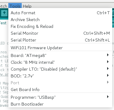
ATmega8 Options
So we have… ATmega8, 8 MHz internal, Disabled (default) and 2.7v. BOD stands for “Brownout Detection” – the chip will stop operating when the supply voltage drops below this value. Not something we’re specifically worried about here. I’ve never messed with LTO, but it stands for “Link Time Optimisation”.
Also note, that near the end of the “Tools” menu, there is a menu option called “Programmer” and I have selected “USBasp”. You should do the same.
Finally, from the menu “File”>”Examples”>”Basics” select the “Blink” example to load it. Replace all occurrences of “LED_BUILTIN” with “0” (excluding quotes). For convenience, you can copy the following into a new sketch if you prefer :
/*
  Blink

  Turns an LED on for one second, then off for one second, repeatedly.

  Most Arduinos have an on-board LED you can control. On the UNO, MEGA and ZERO
  it is attached to digital pin 13, on MKR1000 on pin 6. LED_BUILTIN is set to
  the correct LED pin independent of which board is used.
  If you want to know what pin the on-board LED is connected to on your Arduino
  model, check the Technical Specs of your board at:
  https://www.arduino.cc/en/Main/Products

  modified 8 May 2014
  by Scott Fitzgerald
  modified 2 Sep 2016
  by Arturo Guadalupi
  modified 8 Sep 2016
  by Colby Newman

  This example code is in the public domain.

  http://www.arduino.cc/en/Tutorial/Blink
*/

// the setup function runs once when you press reset or power the board
void setup() {
  // initialize digital pin 0 as an output.
  pinMode(0, OUTPUT);
}

// the loop function runs over and over again forever
void loop() {
  digitalWrite(0, HIGH);   // turn the LED on (HIGH is the voltage level)
  delay(1000);                       // wait for a second
  digitalWrite(0, LOW);    // turn the LED off by making the voltage LOW
  delay(1000);                       // wait for a second
}
Click the “Verify” (tick) button in the top left of the sketch window to make sure the sketch compiles with no errors. If there are errors, double check that firstly, you’ve make the LED pin modifications correctly, haven’t accidentally introduced any errors into the code, and have correctly installed MiniCore. You may also want to check that the correct board settings were selected.
Once / if the code compiles without errors, we’re ready to move on to programming a chip.
Programming a Chip
Ensure the locking mechanism on the development board ZIF socket is unlocked / open (leaver up). Place the ATmega8A chip into the ZIF socket with pin 1 (marked by a little circular indent on the top of the chip) near the reset button (the far end from the 5×2 connector). Lock the chip in place by lowering the leaver on the socket. When soldering the ZIF socket to the board, I recommend ensuring the leaver is at the reset end of the board.
Plug the 5×2 cable connector from the programmer in – one end in the programmer, the other in the development board. Note the notch should face inwards towards the centre of the development board. If it doesn’t, you might have soldered the connector the wrong way around!
<picture>
Taking care not to short the underside of either the development board or programmer on anything metallic (a USB extension cable might help here), plug the USBasp into your computer. You shouldn’t need drivers on a Mac or Linux, but you may have to set up permissions on Linux. Check here for the (permanent version please) solution on Linux.
Bootloader and Fuses
Return to your modified “Blink” sketch. You may want to do a Save As… to keep the modifications for the future. Then, just once, the first time you program your new chip, with the USBasp and development board connected, select the menu item “Tools”>”Burn Bootloader”. This will load bootloader code into your ATmega8, but more importantly, it will set up the various fuses (low level settings) to tell the chip that you want it to operate using its internal 8MHz oscillator and any other settings recommended by the MiniCore software. The IDE should tell you that the bootloader was successfully uploaded. If it didn’t, please check that everything is connected properly and the correct options in the “Tools” menu, as detailed above, have been selected.
The Program
The final, and one of the easiest steps is to load our blink sketch into the chip. This is done by going to the “Sketch”>”Upload Using Programmer” menu item. A shortcut for this is to Shift+Click on the right facing arrow that you would use to ordinarily program an Arduino. If you notice, the “Upload” text to the right of that cluster of buttons changes to “Upload Using Programmer” when you hold the mouse over the Upload button and press the Shift key.
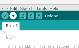
Upload
If you look at the development board, one of the LEDs on the board should now be flashing. This LED is connected to pin 0 on the board. If the LED is not flashing, check the computer screen to see that the program successfully uploaded.
Another advantage of programming a chip in this way is that you do not need the bootloader (when you “Upload Using Programmer” it actually overwrites the bootloader – but retains the fuse settings). This means you can use the full amount of program flash memory in the chip for your own code. While the bootloader isn’t huge, this can make the difference between your software fitting in the chip or not – especially when using one of these cheaper AVRs with less room available to begin with.
Breadboard
Now that you (should) have a program running on the chip, you can transfer the ATmega8A to a piece of breadboard. To recreate the blinking LED circuit in its minimum form, you will need :
- One piece of breadboard long enough to hold the ATmega8A
- Something that can provide 5v
- Two wires for 5v and GND
- A 1k ohm resistor
- An LED
Wire up as follows :
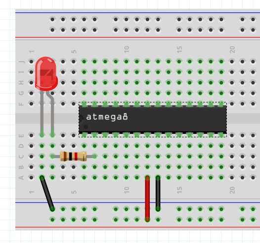
Breadboard
Note that you don’t need the left most black wire as you can just separate the wires on the LED further to bridge back to the other black wire on IC pin 8 (8th pin counting anti-clockwise from the little black dot marking pin 1, not to be confused with Arduino digital pin 8, which is actually IC pin 14… just to confuse things!).
When working on your own projects, you will find the diagram linked here very useful. It details the features and names of various pins on the chip. Note the key item “Arduino Pin” as that is the name of the pin in the Arduino IDE.
Good luck.