By Data Harvest
Data Harvest seem to be one of, if not the last of, the British manufacturers of educational Systems / Control interfaces. I really hope they’re doing well, as interface boxes have always fascinated me and it saddens me to see so many of the companies that make them gone.
I didn’t find any information about Data Harvest interfaces and their serial protocol online so I decided to see if I could brute force the protocol, at least enough to use the interface as I don’t have a copy of any original software. I opened a serial terminal at 9600 baud and mashed some keys to see what it did. I quickly found that it seems to return “Z” as an error code, but responds more interestingly to capital letters. Valid requests are rewarded with either a letter “A”, or an “A” followed by one or more additional bytes. At this point, I switched to a Python test script I wrote which sends sequences of bytes to a port, and prints out the response in hex and ASCII. This allowed me to more carefully study how the FlowGo and then later, the Contact Controller Plus, responded.
While this page doesn’t explicitly discuss the non-plus “Contact Controller”, it is almost certain that they are controlled in the exact same way as the interfaces discussed here, simply with fewer ports than the Contact Controller Plus.
Contact Controller Plus Interface
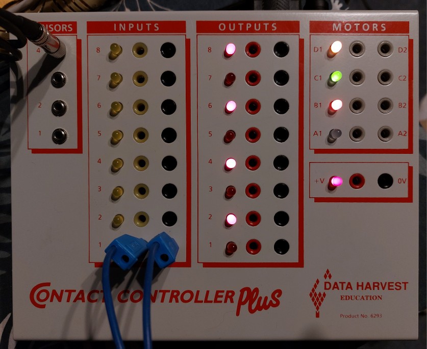
Contact Controller Plus Connectors
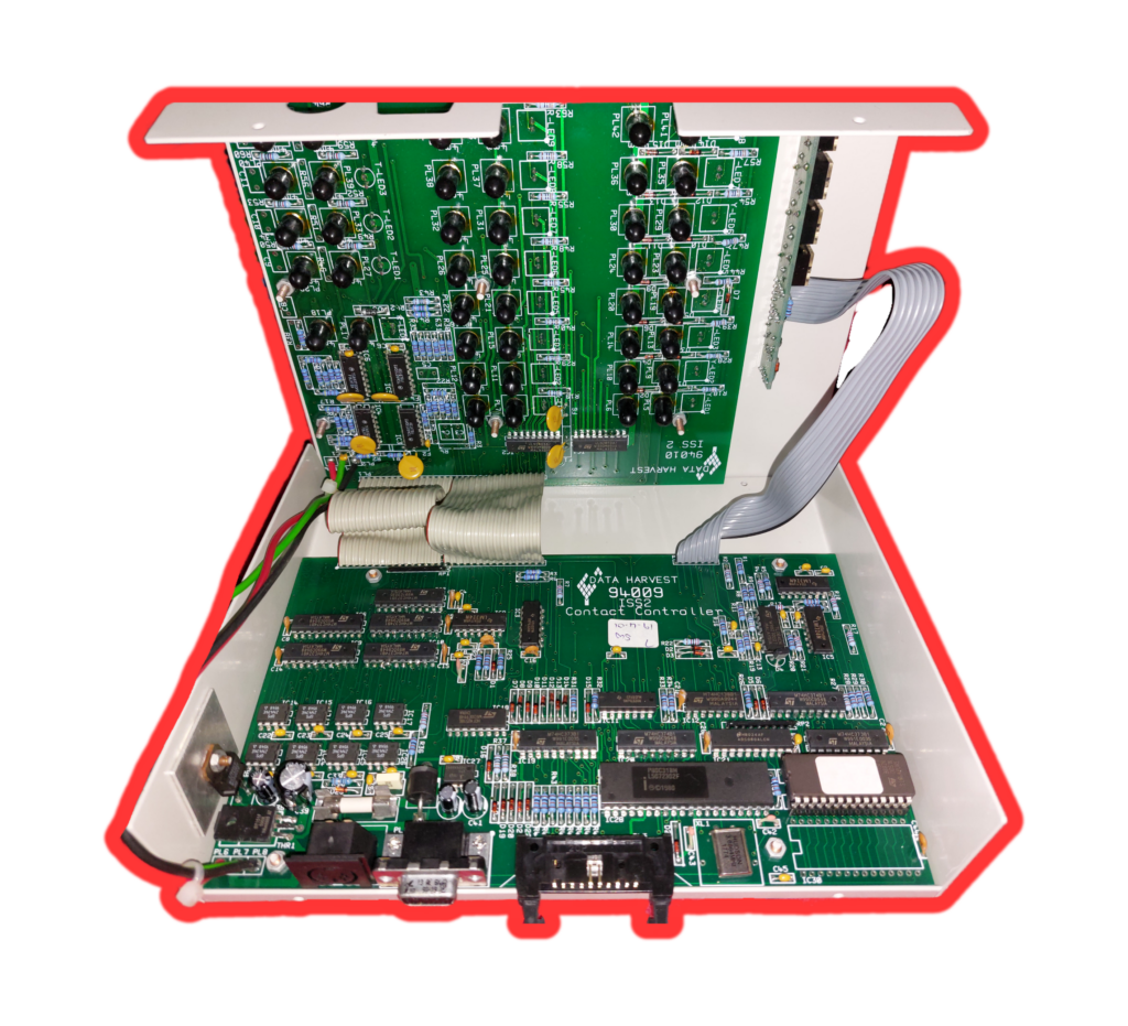
Interestingly, I’ve just made up a power cable for my Contact Controller Plus. I believe this is correct having dismantled it, plus also seen a photo of an original power supply here. Thank you Seldon2k! The default seems to have been either 6v or 7.5vDC, depending on where you look. The logic is run from a 7805, but it seems the outputs operate at a voltage a small amount below the input voltage.
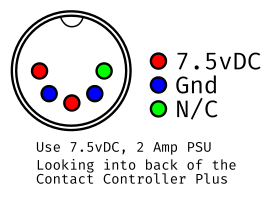
Using the Wayback Machine, I found old references that say the Contact Controller boxes can take input voltages between 6v and 15v and can output up to 5A of power. This is very handy for controlling things like 12V motors or relays – you just pick the input voltage that suits you.
When using my underpowered test PSU, Digital outputs and the motor outputs are around 6v (i.e. a little lower than the PSU voltage) when set high. Keep this in mind if you want to control something with 5v logic, or when calculating current limiting resistors.
The +V output terminal on my box is approximately 6.4v. Don’t draw too much total current (i.e. more than 5A, or the rating of your PSU (including the current used by the box itself internally – whichever is lower), if you want to drive something more than some small 6v motors from the motor outputs and buzzers or something similar from the digital outputs, consider using relays or transistors to buffer the outputs if you can’t provide the correct voltage and / or current.
The Digital Inputs, Digital Outputs and Motor Outputs all use 4mm “banana” jack sockets. The Sensor Inputs use 3.5mm stereo (3 contact) jack sockets. More detail on the sensor inputs is given in the section “Analogue Sensors”.
Dismantling the Enclosure
If you dismantle your Contact Controller / Plus, you may need to replace the plastic push clip / rivets that hold the case together. If you are looking for replacements, you need to get “R2642” clips. I ordered some and they were exactly the right part and identical to what was originally fitted. They’re about £3 for 50 on eBay.
This aside, there are no screws, but you have to bend the case over the serial port in a very worrying way. The cables that attach the top section of the case are folded and attached in a manner that the case opens at the rear. I removed the bottom PCB (but not the top) while working out the power connector pinout. To do so, I had to remove four nuts, one from each corner of the PCB, plus an additional nut on the voltage regulator (on the near left when looking from the back). There is a fuse that may need replacing if someone has blown it in your unit, although I didn’t check the rating of mine as it was not blown. If it is inline with the output terminals (I don’t know if it is), I would expect it to be 5A, otherwise if it is only for logic, a fairly small fuse would be more appropriate (for reference the box draws about 4.8W at idle from the wall using a cheapo variable voltage PSU).
If you plan to remove the two boards on the lid side, remember to unscrew the nuts from the analogue sensor inputs and take care to align the LEDs when putting it back.
Architecture
I haven’t done a detailed study of the circuit boards. In passing I’ve seen a few things. The logic voltage is derived from a 7805 regulator, cooled by being bolted to the metal case. The I/O board has a number of ULN2803A Darlington Pair arrays, these are likely controlling the outputs. This implies 500mA per digital output, so don’t drive anything too big from the outputs.
There are TCA0372 Power Op Amps near the motor outputs. These are rated to 1A, so don’t try to drive a huge motor from the motor outputs.
The ROM fitted to my box is an ST M27C256B 32k ROM that is easily read with a basic TL866 II Plus EEPROM reader.
The interface uses an Intel MCU, specifically the 80C31, which is similar to an 8051, but I assume CMOS and without internal ROM. This is handy because it makes it easier to remove / read / replace the ROM in these machines.
The ROM
If you are working on your Contact Controller / Plus, I would appreciate if you sent a copy of your ROM chip if it is different to mine. Mine is dated June 1994 and version “Contact Controller B 07”. What is interesting is that the ROM only contains about 1050 bytes of code. The ROM chip itself is a 32k chip, so only 3.2% of the chip is used! Further to this, there is an unpopulated footprint for a second chip next to the first. I wonder did they offer, or plan to offer, additional software modules for specific applications. Perhaps fitting two 16k ROMs instead of one 32k ROM with “Pro” features in the second ROM? If anyone knows, I’d be interested in finding out.
A possible future project suggested by a friend would be to flash a ROM with BASIC 8031 on it. Perhaps with a little work, it would be possible to add a command to the existing command set that jumped to 16k in the ROM. Additionally, perhaps it would be possible to call the existing commands from BASIC. The interpreter would need to run over the serial interface.
Further to the above, might it be possible to add a RAM chip to the unpopulated footprint to enable the temporary storage of larger programs? All fun possibilities.
Contact Controller Plus Communication
See the section on “The Serial Protocol” for a detailed breakdown of known commands.
The Contact Controller Plus (and likely the Contact Controller) uses the same serial commands as the FlowGo. One thing to note though, I suspect they are doing the serial in software on the 80C31 MCU, and don’t have any buffering. I had to put a short pause between bytes sent in my code otherwise it confused the box sometimes.
So far I have confirmed the following commands are identical, with the exception that they use more bits of the bytes in the instances where the FlowGo only uses a portion of them, due to there being a greater number of ports on the Contact Controller. For example, the motor outputs still use two bits per pair of outputs, but now there are four pairs, making up the full byte. This makes perfect sense.
- Analogue Sensors
- Digital Inputs
- Digital Outputs
- Motor Outputs
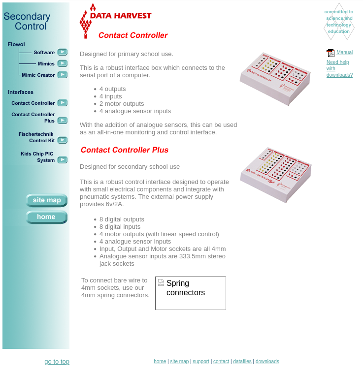
Here is a screenshot from the wayback machine of Data Harvest’s page for the Contact Controller, and Contact Controller Plus. Sadly, the manual was not captured. If anybody has a copy of the manual, I’d really appreciate it.
Compatibility
The Contact Controller works with vintage Macintosh serial ports, and has been tested with an LC 475.
The FlowGo Interface
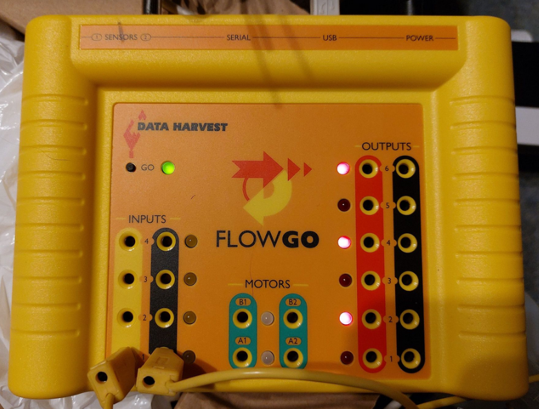
There are at least two versions of the FlowGo Interface, one only has a USB port, the other has both a USB and an RS232 port (serial). This said, on my dual port version the USB port is a FTDI USB to serial adapter and shows up on the host computer as a serial port / COM port.
Find a copy of the two manuals I’ve found here and here.
The FlowGo supports running a saved program while disconnected from the host computer, but unfortunately, I suspect it will be very tricky to work out how this works. I haven’t dismantled my FlowGo yet, I’d be interested to see the circuit and if it gives any clues, but I don’t suspect it will. I find myself wondering if Data Harvest would be willing to share information, but they haven’t answered my previous emails.
The FlowGo appears to be very similar, in terms of functionality, to the Contact Controller, except for having fewer analogue sensor inputs and more digital outputs. At this point in time, I assume the Contact Controller and Contact Controller Plus also don’t support operating independently with a saved routine.
FlowGo Connectors
My FlowGo came with a 6V, DC, centre positive power supply with a barrel jack. Your power supply should be able to provide 2A. It is not possible to power the FlowGo from USB.
There are two “sensor” inputs on the back which use 3.5mm stereo audio jack style connectors. See the later section “Analogue Sensors” for details regarding how these sensors are wired.
Digital outputs and the motor outputs are around 6v (i.e. the PSU voltage) when set high. Keep this in mind if you want to control something with 5v logic, or when calculating current limiting resistors. If you’re building something for other people, I’d actually recommend designing for 6v to 7.5v, because some other interface models from Data Harvest use a 7.5v PSU. Don’t draw too much total current, if you want to drive something more than some small 6v motors from the motor outputs and buzzers or something similar from the digital outputs, consider using relays or transistors to buffer the outputs. This said, the manual mentions that there is a self resetting fuse in the supply to the outputs (keep in mind this wouldn’t help with exceeding the rating of an individual output).
The manual says not to use a power supply rated for more than 2A, so it looks like the total power draw of the device including outputs is rated at that. Helpfully, the manual says that the total current available at all outputs is 1.3A and that individual outputs can output 500mA each (it doesn’t clarify, so this is assumed to be both the digital and motor outputs).
Compatibility
For an unknown reason, the FlowGo doesn’t work with vintage Macintosh serial ports. It is possible that this is a result of both the host and the box being technically non-compliant as Macintosh serial isn’t fully compliant with the RS232 standard, and I have a suspicion that the same is true of some FTDI RS232 chips operating on 5v in the late 90s and early 2000s.
Working with your Data Harvest Interface
The remainder of this page describes how to work with your Data Harvest Interface when writing your own software or by poking it over serial, whether it is a Contact Controller, Contact Controller Plus, FlowGo, or possibly some other similar serial or serial-over-USB devices they have made through the years. This does not include things like the EasySense Q – these dataloggers have a different set of commands and seem to be a bit more complex. I have made a little progress with the EasySense family, but I got distracted with these!
For the most part I have assumed you will be sending commands and parameters as hex values, but this isn’t the only way to do it. Most if not all of the commands are actually in the range of ASCII capital letters and can be typed, but the data that may need to send with them, and the responses will not be so convenient for a serial console.
The Serial Protocol
Valid commands that I found are between 0x42 and 0x59 (i.e. in hex). Some require a second byte to follow (as expected for doing things like setting the state of digital outputs). The following are the commands I have found as well as what I currently know about those commands. There is enough here to write some useful software – at some point I will write a python library to use the box, but I haven’t got that far yet.
In the following table, the format column describes the command that needs sending. Each section in square brackets is a byte, <0-3> is a number between 0 and 3 inclusive, <x> is any number that can fit in a byte. <x*n> is n bytes. Letters in quote marks are an ASCII part of a response, things like CR and DC1 are ASCII control characters. + is used to represent concatenation and doesn’t represent anything in the actual response from the interface box. There may be errors as I’ve only done a quick investigation so far. There are very likely to be specific situations in which different responses are obtained. There is more work to be done!
| Command | Format | Example Response | Description |
|---|---|---|---|
| 0x42 | [0x42] | “A” + “FLOWGO” + [CR] + [DC1] | The FlowGo responds with its name. |
| 0x43 | [0x43] | “A” + “@” | Possibly firmware or hardware revision? My FlowGo reports 0x40, while my Contact Controller Plus reports 0x80. |
| 0x44 | [0x44] | “A” + [<x>] | Digital Inputs. All off = 0xFF. |
| 0x45 | [0x45] | “A” + [0x00] | Unknown. 0x00 on FlowGo, 0xC0 on Contact Controller Plus. |
| 0x46 | [0x46][x] | “A” | Digital Outputs. All On = 0xFF. |
| 0x47 | [0x47][x] | “A” | Motor Control – LEDs are bi-colour LEDs and give Green/Red/Orange indications. See the “Motor Control” section. |
| 0x48 | [0x48][x] | “A” | Expansion Port Control. See “The Expansion Port” section. |
| 0x49 | [0x49] | “A” + [0x00] | Unknown (Can drop the serial connection and needs a power cycle) |
| 0x4A | [0x4A] | “A” + [0x00] | Unknown. (Replies 0x00 from FlowGo, 0xAA from CCP) |
| 0x4B | [0x4B] | “A” + [<x>] | Returns the status of the Expansion Port outputs as set. |
| 0x4C | [0x4C][<0-3>] | “A” + [<x>] | Unknown – Possibly only 0 to 3 valid on FlowGo, more valid on CCP. |
| 0x4D | [0x4D][x*n] | Various | Unknown |
| 0x4E | [0x4E][x] | “A” | Motor Speed. See the “Motor Control” Section. |
| 0x4F | [0x4F] | “A” + [<x*5>] | The 2nd and 3rd bytes are Sensor 1 and Sensor 2 Analogue values as single bytes. |
| 0x50 | [0x50] | “A” + [0x00] | Unknown. |
| 0x51 | [0x51] | “A” + “FLOWGO” + [CR] + [DC1] | Reset? Or same as 0x42? |
| 0x59 | [0x59] | “A” | Runs through a sequence on the digital and motor outputs. |
The most obvious thing that I don’t have any information about is the “Go” button on the FlowGo (I checked and it isn’t counted as a digital input).
An Example Program
Here is a quick example Python program I modified from one of my previous projects. It just counts in binary on the Digital Outputs.
The code is as follows, note that you will need to install the required libraries as appropriate, set port permissions, and replace the serial port in the code with the correct one for your setup.
# Data Harvest Contact Controller Test Program
# By Phil
# https://elephantandchicken.co.uk/stuffandnonsense
# 20241117
# This is an test program to blink some LEDs
# on the Data Harvest Contact Controller Plus
# Interface, using Python 2.
#

import time
import serial

ser = None

def open(port):
	global ser
	ser = serial.Serial(port, 9600, timeout=1)
	return ser.is_open

def close():
	global ser
	if ser.is_open:
		ser.close()
	ser = None

def d_out( val ):
	global ser
	if ser.is_open:
		ser.write(chr(0x46))
		time.sleep(0.01) # give it a chance to process
		ser.write(chr(val))
		time.sleep(0.1) # give it a chance to reply
		readByte = ord(ser.read(1))
		while ser.inWaiting() > 0:
                        print "Additional bytes : " + str(ord(ser.read(1)))
		return val
        else:
                raise NameError('Serial connection not open - try calling open(xyz) first')

open('/dev/ttyUSB0') # <--------- edit this line to reference your serial port

i = 0

try:
	while True:
		print "Press Ctrl-c to exit.   Digital Outputs : " + format(d_out(i), '0x')
		i = i+1
		if i>255:
			i=0
		time.sleep(0.1)
except KeyboardInterrupt:
	print "Exiting..."
	d_out(0)
	close()
	print "Done."
Python Program for Manually Sending Commands
This program runs in Python 2 and enables you to manually send commands to your Data Harvest (or other) serial interface box. Commands and data are sent as parameters from the command line, so if you save this program as “FlowGo.py”, you would type “python2 ./FlowGo.py 46 FF” to send command 0x46 with the data byte 0xFF. Note you don’t need to include “0x”. If you want to send more than one command, you can just keep stringing them together. For example, to set the outputs and read the inputs in one go, you would run “python2 ./FlowGo.py 46 FF 44”.
You will need to make sure the required libraries are available, the correct version of python is installed and that you have the appropriate permissions. Additionally, the format I wrote the incantations above assumes you’re using Linux or macOS, and have navigated to the same folder as the program. On Windows, this may be slightly different.
# Data Harvest Contact Controller Command Sender
# By Phil
# https://elephantandchicken.co.uk/stuffandnonsense
# 20241117
# This is an test program to manually send commands
# to the Data Harvest Contact Controller Plus
# Interface, using Python 2.
#

import sys
import time
import serial

if len(sys.argv) > 1:

   ser = serial.Serial('/dev/ttyUSB0', 9600, timeout=1) # <--------- edit this line to reference your serial port
   print "Connected..."
   print "Sending command(s)..."
   for n in range(1, (len(sys.argv))):
      print str(n) + " : " + str(int(sys.argv[n], 16))
      ser.write(chr(int(sys.argv[n], 16)))
      time.sleep(0.01)

   time.sleep(1)

   readTxt = ''
   print "Reading back..."
   while ser.inWaiting() > 0:
      nextvalue = ser.read(1)
      readTxt += nextvalue
      print ord(nextvalue)

   if len(readTxt) > 0 :
      print readTxt
   else:
      print "No response"
   ser.close()
else:
   print "error"
Digital Inputs
All inputs are read in at once as a byte, triggered by the 0x44 command. The response starts with an “A” like all valid commands, and then a second byte representing the current status (on or off) for all inputs. On interfaces where there are fewer than 8 digital inputs, the command functions identically, except the higher order inputs are not there.
The only confusing thing with the digital inputs is that the logic feels like it is reversed. When all inputs are logic level low, or not connected to anything, the command gives the response 0xFF. While this seems strange, there is a sensible reason for it. Because the inputs are designed to work with simple switches, what they actually detect is a short from the output terminal to ground. This means that the inputs are held high with a pull-up resistor until you press a switch, at which time the input drops to low. The end user likely wouldn’t normally be fully aware of this when using commercial software.
Another implication of this is that if you wish to drive the inputs from an external circuit, you need to make sure that you drive them low, and make a decision about how you will interpret the readings. If you use an external circuit to drive all inputs low, all the indicator LEDs will light as if they’re saying “high”, and command 0x44 will read 0x00 (sensibly), but if you tristate the connection, they’ll all go high. It is important to consider this slightly unusual behaviour.
Each bit of the returned byte corresponds to an individual input, with the LSB (Least Significant Bit) being for input 1. This means that if input 1 is high, and all others are low, you would read in the value 0xFE. The following command and response show what happens if input 4 is “on” (when digital input 4 is shorted to the ground terminal next to it (or any other ground terminal)).

The response 0xf7 is equivalent to b11110111 in binary (LSB on the right), so you can see that the 4th bit from the right is 0.
Digital Outputs
Note that on the Contact Controller Plus (and likely Contact Controller) the digital output ports read as “high” even when set to low. They probably float high when there is no load. With this in mind, if you’re using them to drive low power logic, it is probably worth adding a small dummy load to ensure that you get valid logic levels. A 10k 1/4 watt resistor between the terminals is probably enough.
Otherwise, using the digital outputs is trivial. The digital output command is 0x46 followed by a single data byte. Each bit in the byte corresponds to one of the outputs, so 0xFF is all on, 0x00 is all off, 0xAA is every second LED and 0x01 is just the lowest numbered output on. You can’t toggle a single output with this command. Boxes with fewer outputs work exactly the same, just with the higher number outputs missing. The following command would set the 3rd output high, and all others low.
0x46 0x04Analogue Sensors
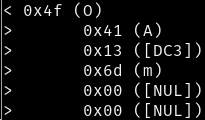
When the command 0x4F is sent to the interface, both interface types respond with five bytes. The first is the “A” which is always sent in response to a valid command, and the remaining four represent a value (between 0 and 255) for each sensor in order. On boxes that only have two sensor inputs, you can just ignore the last two bytes. The following shows the command being sent, and the reply being received :
The analogue sensors use a stereo mini jack (3.5mm jack). Having measured the resistance between the different parts of a temperature probe, I believe that the temperature probe is a potential divider with a 100k NTC Thermistor and a 100k resistor. I anticipate that they are wired as follows :
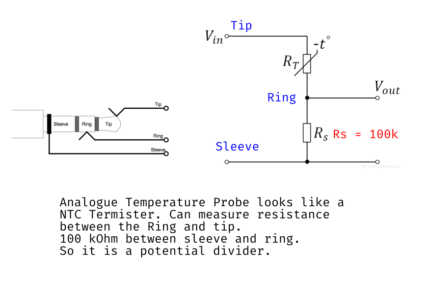
The Data Harvest LDR I have uses a 270k Ohm fixed resistor in its potential divider. I’m not certain of the specification of the LDR itself. In general, it should be easy to create your own sensors using other resistive sensors.
Motor Control
Enable / Direction
Each of the four motor channels, A, B, C and D (only A and B exist on the FlowGo and vanilla Contact Controller) have four main states.
- Off (Both outputs low)
- Forwards (1 low, 2 high)
- Backwards (1 high, 2 low)
- Off (Both outputs high)
The two different “off” states are useful if you want to use the motor outputs as additional digital outputs or as analogue outputs.
The motor control command, 0x47, is sent with a following additional byte, which the 2 LSBs (least significant bits) of which represent the status of motor output “A”. The next two bits are for output “B”, then “C”, and lastly, the two most significant bits are for motor output D. In the following diagram, only outputs A and B are shown, as used on the FlowGo and non-Plus Contact Controller.
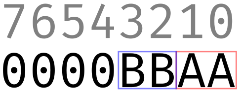
In the diagram above, bit 0 represents motor output terminal A2’s status specifically, bit 1 represents terminal A1’s status, 3 is B2, and 3 is B1. On the Contact Controller Plus, this continues for C2, C1, D2 and D1 respectively, from bit 4 to 7.
To run motors A and B in the forward direction (assuming A2 and B2 go to the positive terminal of the motor), you would want to send the binary number B00000101, which is $5 in hex and 5 in decimal.
If no speed data has previously been sent, the outputs will default to 100%.
Setting the Motor Speed
The motor outputs are actually handled as eight independent analogue outputs, which can be set between 0 and 100% in 10 steps. It is unclear whether the percentage is of voltage, or corrected to give motor speed characteristics but looking with a voltage meter, it doesn’t seem very linear. To set the analogue value of one of the eight outputs (four on the non-Plus Contact Controller and FlowGo) you send the command 0x4E, followed by a data byte. It is only possible to change the value of a single output at a time. The data byte is made of two parts or 4bit nibbles. The least significant nibble represents which output you want to set the speed for as a number between 0 and 7, corresponding to the output in the sequence A1, A2, B1, B2, C1, C2, D1, D2. The most significant nibble represents the “percentage” as a value between 0x0 and 0x9 – each number represents an approximate step of 10% (the maths on this doesn’t quite make sense as there are 11 positions between 0 and 100% inclusive, but I’ve checked, and there is no visible difference in voltage between 0x9 and 0xA).
For example, to set output B2 to approximately 50%, you need to send 5 to the 4th output (i.e. A1, A2, B1, B2). Given we are counting from zero, and the output goes in the least significant nibble, that means we want to send the hex value 0x53. This means the full command to set B2 to 50% is 0x4E 0x53.
While it is possible to set both of a pair of motor outputs to arbitrary values, when driving motors it would be more normal to have one output set to zero or off. As such, to set all four outputs to 50% forward, you would send the following sequence.
0x4E 0x50 - Set output A2 to 50%
0x4E 0x52 - Set output B2 to 50%
0x4E 0x54 - Set output C2 to 50%
0x4E 0x56 - Set output D2 to 50%
0x47 0x55 - Enable all motors in the forward direction
This assumes that the positive terminal of each motor goes to the “1” output (i.e. “A1” etc.).
The Expansion Port
An expansion port is available on the Contact Controller and Contact Controller Plus, as well as some other boxes made by Data Harvest. I’ve not found any information about what exactly can be connected, or how it is controlled, but made a guess and seem to have mostly worked it out.
The physical port is a keyed 20 pin IDC connector with latches. My first thought would be to check if it has been wired in a similar fashion to the User Port on a BBC Micro, the logic being Data Harvest’s history producing hardware for Acorn computers. This would enable Data Harvest to have continued to use previous designs originally intended for the User Port on a more modern PC / Mac that only had a serial port. I plugged in an IDC cable and prodded the various pins and was able to confirm that yes, 5v was available on the User Port 5v pins, and all the User Port ground pins were ground. Given this, I picked a random pin that would be an I/O pin on the User Port, and tried some of the remaining unknown commands, being sure to pick ones that required a data byte… one of them was able to toggle the pin I was watching!
If the pinout matches the User Port, this perhaps offers some fun opportunities to connect some old Deltronics Buffer Boxes to the port for additional I/O!
I made a little LED board and connected them to each of the eight pins I expected to be user pins and powered it up. Unfortunately, I discovered that there are only six pins that work as outputs. The missing pins don’t seem to be damaged as the numerical sequence of outputs skips over them. I have shown them as purple in my diagram.
Warning – Two of the pins don’t seem to behave as would be expected on a BBC Micro User Port. The following image indicates how I believe the port is wired. For safety, until I have full confidence, I did not bridge the Gnd or 5v pins together.
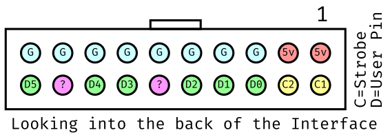
It is also worth noting that the digital pins on the expansion port have very low output voltages, only reaching about 2.7v for logic high. My suspicion is that this has been done intentionally to match the characteristics of the BBC Micro, as the 6522 VIA chips don’t produce very high logic high output voltages. The datasheet for the 74HC373 latch chip they have used suggests that it would be capable of higher voltages than this.
Warning! The 74HC373 latch chip they have used to drive the port can only source currents of up to 50mA absolute maximum, and only 20mA maximum per pin! As such, don’t draw too much current.
The User Port on the BBC Micro offers both inputs and outputs by setting a register in the 6522 VIA chip, I’m not sure if this is also possible here. It could be. It feels likely that another command might read the pins, or set the direction.
Writing to the Expansion Port
To write to the expansion port, you should use the command 0x48, followed by a data byte. The data byte bits represent the pins as labelled in the diagram above, with bits 6 and 7 being apparently ignored because they do not have corresponding pins. I’m unsure what, if anything, can be done with the unknown pins and the strobe pins.
Reading the Current Expansion Port Output Value
It is possible to read back the value that has been currently written to the expansion port with the command 0x4B. If you send the value 0x01 to the expansion port using 0x48 0x01, and then you send 0x4B, the interface box will respond with 0x01 (after the usual “A”). This is true for any value you write to the expansion port, even including the bits 6 and 7 which don’t appear to have corresponding pins on the connector.
This command may be more useful if it is possible to switch the port to be an input perhaps?
Things to Do and Investigate
- Why does command 0x49 drop the serial connection on the Contact Controller Plus (but I don’t think on the FlowGo)? Is it changing the serial speed or mode in some way?
- What is going on with the strobe and two unknown pins on the expansion port?
- How does the saved routine functionality work on the FlowGo?
- Have I done harm by poking values into the void that is 0x4D?
- What on earth is 0x4C?
- Is 0x43 the firmware version?
- What is 0x45?
- Why is 0x4A?
- Who is 0x50?
I need to write a Python 3 library to make these boxes useful when you buy them from eBay and they don’t come with any software. The issue is that they were generally sold with a site licence, so there was probably only a single disk in the IT office and when equipment was sold off, they weren’t together. Truth be told, these boxes would probably be less interesting if I didn’t get the fun of working out how they work. It does worry me that certain features are effectively impossible to work out though. Given that, please get in touch if you know anything I’ve missed in my investigation! Manuals, specifications, adverts and knowledge all welcome!
Other things to add to the page…
- How to add more outputs or inputs with shift registers.
- How to control higher power devices with relays.
- How to control a stepper motor.
Addendum
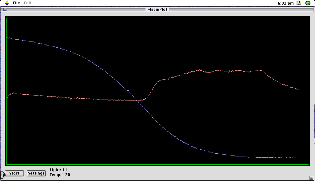
Here is a short video of the Contact Controller Plus capturing light and temperature levels from a 1993 era Macintosh 475 and Mac OS 7.5.3. The software is just simple program I wrote to fetch the values over serial and then draw a graph. Nothing is to scale and the values aren’t in any particular units.
The following is about an hour of samples taken every 4 seconds over sunset. The blue line is from a light sensor pointed out the window, and the red line is from a temperature probe shoved in a radiator and showing the central heating cycling (the primary cycle is the room setpoint, the little waves at the top are the boiler regulating the temperature of the water in the heating circuit).
