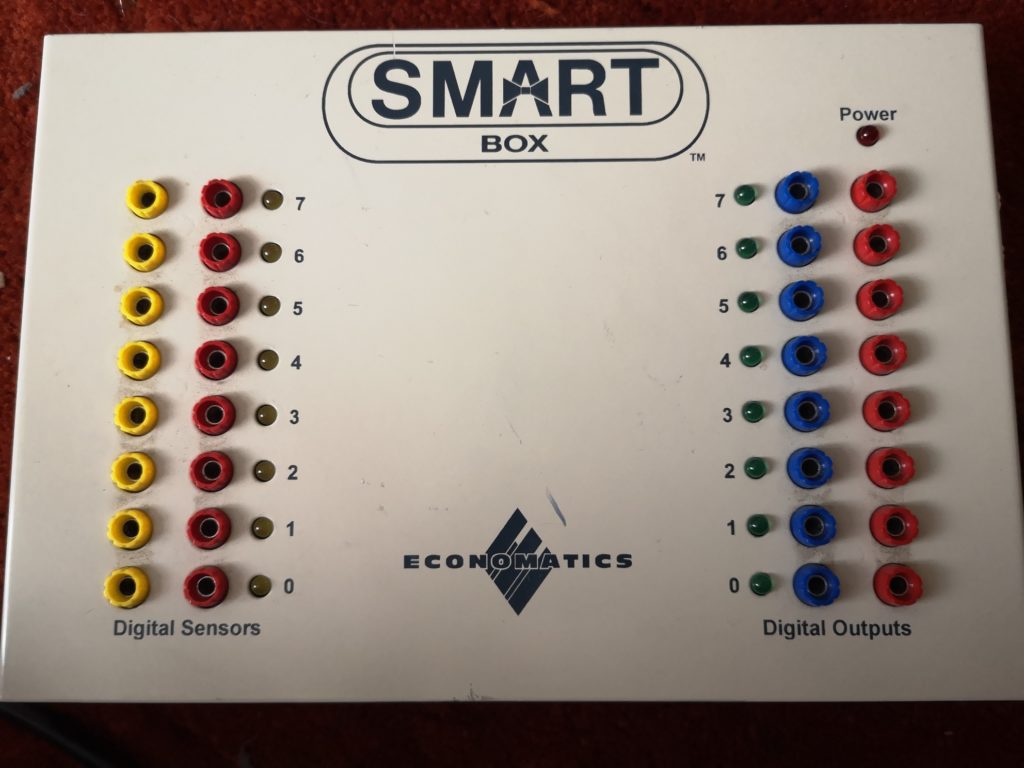
Working with the Economatics Smart Box Serial Interface on a Modern Computer
Well, I had all sorts of fancy plans for how I would reverse engineer the serial protocol to control my ebay purchase “Smart Box” (some of which I will document at some point as they’re useful). Ultimately, I had so much difficulty installing MS .net 1.1 in Wine / PlayOnLinux that I went back to trawling the internet looking for alternative software to wire tap.

I struck gold when I found the following website :
http://old.ftcommunity.de/ftComputingFinis/smartboxe.html
The website includes a download of example code, the core of which is in VB6 and includes many serial commands for controlling the Smart Box (SB-04 version – I understand that older versions work differently, so be warned!), as well as an instruction manual that goes some way to explaining how the box data formats work.
After a bit of messing about in Python, it was fairly trivial to test a number of commands and witness the results. The only major feature I’m not currently sure about is the Analogue Inputs – I don’t know what the pinout is of the 5 pin DIN sockets, and so can’t easily test them. Perhaps a bit of circuit board investigation will help with this.
In summary, I have found the following :
| Description | Command | Parameter | Response | Python Example |
| Set All Motors | 10 | 8 bit value. Note, each pair of bits represents a motor. 01=left, 10=right and 00=stop | n/a | ser.write(chr(10)+chr(0b01010101)) # rotate all motors to the left |
| Motor <x> Left | 12 | 1 to 4 | n/a | ser.write(chr(12)+chr(1)) # rotate motor ‘A’ to the left |
| Motor <x> Right | 13 | 1 to 4 | n/a | ser.write(chr(13)+chr(1)) # rotate motor ‘A’ to the right |
| Motor <x> Stop | 14 | 1 to 4 | n/a | ser.write(chr(14)+chr(1)) # stop motor ‘A’ |
| Set All Digital Outputs | 20 | 8 bit value | n/a | ser.write(chr(20)+chr(0b11111111)) # turn all digital outputs on |
| Get Analogue <x> | 40 (TBC) | 1 to 4 | 8 bit value?? | ser.write(chr(40)+chr(1)) # send me analogue input ‘A’ |
| Set Low Resolution Analogue | 45 (TBC) | n/a | n/a | ser.write(chr(45)) # set low resolution analogue mode |
| Get All Digital Inputs | 90 | n/a | 8 bit value. Note the command seems to respond with three bytes, although the first identifies the status of each input. | ser.write(chr(90)) # send me the status of the digital inputs |
| Get Digital Input <x> | 91 (TBC) | 1 to 8 | 0 or 1 (in 8 bit value) | ser.write(chr(45)+chr(1)) # send me the status of digital input 0 |
The following example switches on motor ‘A’ for 5 seconds, stops it for 0.5 seconds, runs it backwards for 2 seconds and then stops it. Note the serial port will need setting – I have used ‘/dev/ttyUSB0’ as this is the correct port for my USB to RS232 adapter on my Linux machine.
#!/usr/bin/python

# https://elephantandchicken.co.uk/stuffandnonsense
# 04/03/2020

import time
import serial

# This example tests motor output A

ser = serial.Serial('/dev/ttyUSB0', 9600, timeout=1)

ser.write(chr(12)+chr(1))
time.sleep(5)
ser.write(chr(14)+chr(1))
time.sleep(0.5)
ser.write(chr(13)+chr(1))
time.sleep(2)
ser.write(chr(14)+chr(1))

ser.close()
The following example reads the status of all digital inputs (aka “Digital Sensors”) 20 times.
#!/usr/bin/python

# https://elephantandchicken.co.uk/stuffandnonsense
# 04/03/2020

import time
import serial

# This example reads in the digital sensors and displays their status

ser = serial.Serial('/dev/ttyUSB0', 9600, timeout=1)

# Flash Digital Outputs to show that the program is running
ser.write(chr(20)+chr(255)) # all on
time.sleep(0.1)
ser.write(chr(20)+chr(0)) # all off
time.sleep(0.1)

i = 0

while i < 20:
	ser.write(chr(90)+chr(1)) # request digital input status
	time.sleep(1) # wait (ages) for the response
	readVal = 0 # clear variables
	readByte = 0
	readByte = ord(ser.read(1)) # read the first waiting byte in the buffer
	while ser.inWaiting() > 0: # if there is more data in the buffer
		readVal = ord(ser.read(1)) # read it to clear it
	print "result : ",format(readByte, '08b') # print the first byte in boolean format
	i+=1 # increment counter for the while loop
ser.close()
I still have some more work to do, regarding confirming exactly how these commands work (for example, what are the second and third bytes from the digital read response?). Additionally, I suspect that it is possible to set the voltages, but don’t know how. I’m (absolutely) guessing that command 11 might be motor speed.
Additionally, please contact me if you know any more details of the control scheme, or the analogue port pinout.