The DualClock PCB enables you to easily overclock an A3010 (and some other classic computers such as the Macintosh Quadra 700), while adding the ability to switch between multiple speeds. In the specific case of the A3010, three speeds are available as disabling both clock sources on the DualClock causes the computer to revert to its existing clock signal, derived from the 72MHz clock.
It is easiest to add the DualClock to an A3010 if you have a later revision logic board, as these have a pre-existing footprint for an additional clock.
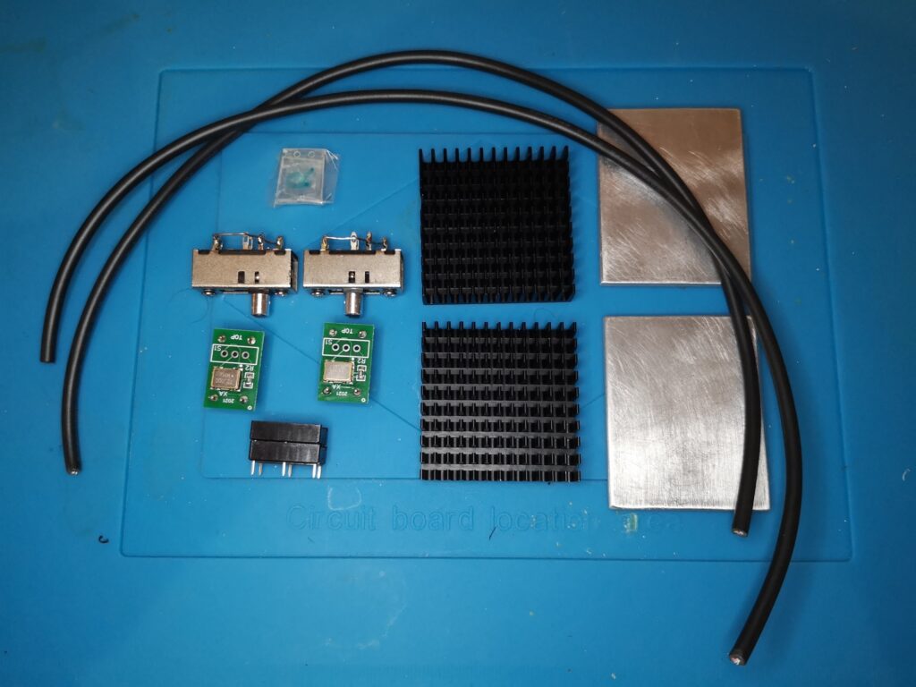
To add a DualClock PCB to a later revision A3010, you will need the following :
- An A3010 and permission to modify it
- A DualClock board with or without a built in switch
- Screw drivers to dismantle the A3010 and remove the logic board
- A reasonable soldering iron
- Solder
- Flux
- Solder wick
- A 22R 0805 surface mount resistor
- A 14pin dip socket (recommended)
- A fast 4MB RAM upgrade (recommended)
- Heatsinks for the Processor and RAM (recommended)
First things first – check your battery – if the machine has its original battery, remove it with a pair of side cutters. These batteries leak and cause computer-destroying corrosion, which removes traces from the logic board. Replacements can be obtained. If the battery appears to have been leaking, thoroughly clean the surrounding area with an non-static brush and IPA (Isopropanol alcohol, not the beer).
Clear the Existing Solder
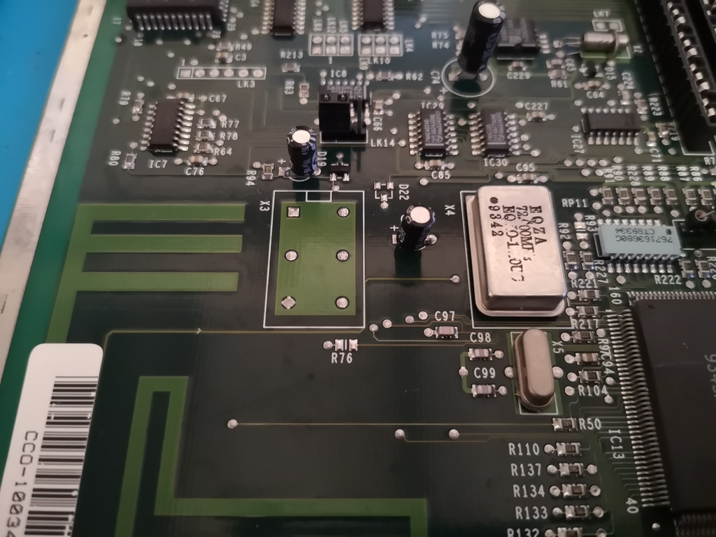
Find the clock footprint labelled “X3” on the logic board. This is between the main ARM250 SOC and the front of the logic board. It has 6 pads, which are likely flooded with solder. Also note the unpopulated “R76” resistor footprint to next to X3 – this is where we will be adding our 22R 0805 resistor.
Firstly, apply some flux to each of the 6 pads on X3. Counter-intuitively, the next thing to do is add some more fresh solder to each of the pads. Then add a bit more flux again – try to keep a bit of flux on the pads at all times when you’re working with them, as it helps the solder flow better.
Place the solder wick on top of the first pad, and the iron on top of the solder wick, don’t leave it on for more than a few seconds and lift both the wick and iron together. Once you feel the solder go into the wick, check to see if the pad is now clear of solder – if it isn’t, you might want to try from the other side (by turning the board over). If it still isn’t clear, add more solder and try again, you don’t want to put too much heat into the board, so never keep the solder melted for a long period of time, if the solder is molten and it isn’t being drawn into the wick, holding it there for ages isn’t going to make any difference. Just add more solder and start again.
Keep doing the above until all 6 pads are cleared of solder and you can see through them.
In the photo above, I have all but one pad clear. You can see the mess of the flux that I’ve been using to keep the solder flowing well.
Next, apply some flux to R76 and use the solder wick to remove the excess solder on its two pads. With that done, you’re ready to start adding components.
Adding the Resistor and Socket
The resistor should be a 22R (22 ohm) part, in this 0805 package, a 22R resistor is labelled “220” on the top, meaning 22*(0*10) (a 222 resistor would be 22*(2*10), or 2200 ohms). Do not mistake a resistor labelled “220” as a 220 ohm resistor!
My usual technique for adding this type of small resistor is to put a small amount of solder on the pad closest to my soldering iron hand, and then taking the resistor in a pair of tweezers (they’re not polarised) push it into place while reflowing the solder on the one pad with the iron. Solder the other end, and then perhaps using a little flux, touch the first end with the iron again to tidy it up if it is messy.
Using a pair of small needle nose pliers, I pushed the 8 unused pins upwards and out of their seats on the 14pin socket, leaving only the four end pins and two centre most (total of 6) to match the X3 footprint. Make sure the socket orientation matches the footprint, with the notch at the same end as the notch shown on the silkscreen on the PCB. When soldering sockets in place, I usually solder one corner pin, make sure it is flush with the PCB, and then solder the opposite corner. Once those two are sat flush, I solder the others.
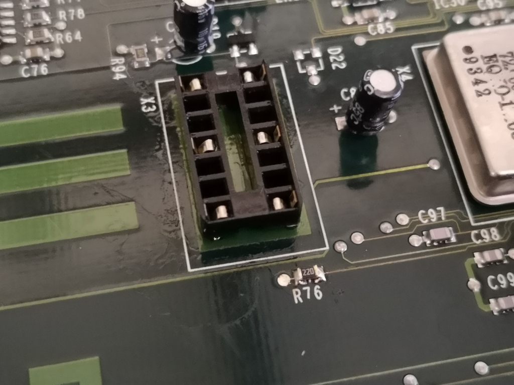
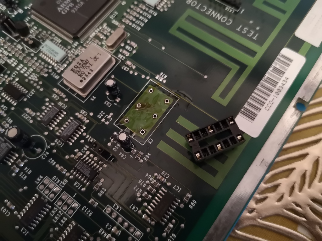
The photo above shows R76 and X3 populated. At this point you might want to clean away the flux with some IPA.
DualClock with Integrated Switch
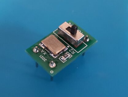
If you have a DualClock with an integrated two way switch (as above) then you’re almost ready to go. Note the small white circle next to one of the corner pins. This goes at the end of the socket closest to the notch. Plug the DualClock in, reassemble the computer and you should be ready to go. Looking at the DualClock with the text oriented correctly, left should be the faster speed, and right the lower speed of the two available. To revert the A3010 to its default speed, simply unplug the DualClock from the socket (and store it safely).
DualClock with a Remote Switch
A remote switch can be wired in to allow the computer’s speed to be changed without opening the case. A remote switch should not be switched while the computer is powered on as it will likely result in a crash, or unpredictable behaviour. A simple SPDT (single pole, double throw) switch is attached in a similar manner to the integrated switch above, with the common to the centre of the three positions.
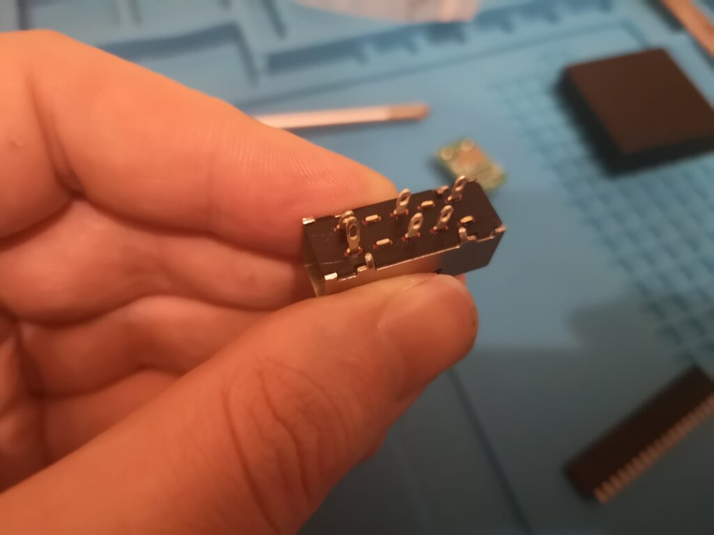
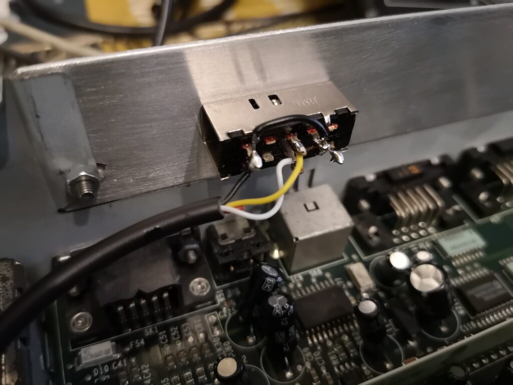
A more advanced solution is to use a DP3T (double pole, triple throw) switch. In the picture above, I have snipped off the unused terminals, the left most pair are position 1, the second from left are the two common pins (one for each row of contacts, isolated from each other), the single contact in the third column connects in the middle switch position, and the right most contact is connected in the third switch position. This switch makes it possible to disable both clocks on the DualClock, meaning an A3010 reverts to its original clock source. Doing this gives you three speeds from an external switch. I wired the switch I have been using as follows :
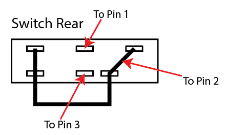
With this configuration, the three positions of the switch give Low, Medium and High speed. The black wire shown connects the 4 contacts in a way that disables the DualClock as required for each position. The labels “To Pin 1”, “To Pin 2” and “To Pin 3” show how this switch should be wired into the DualClock itself. The pin numbers correspond to the following on the DualClock itself :
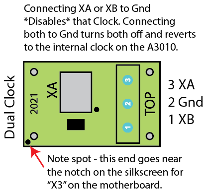
Please ignore the exact wiring of the switch in the photo below as it is the prototype, and I got “Medium” and “High” speed back to front (whoops). Instead follow the wiring in the drawings.
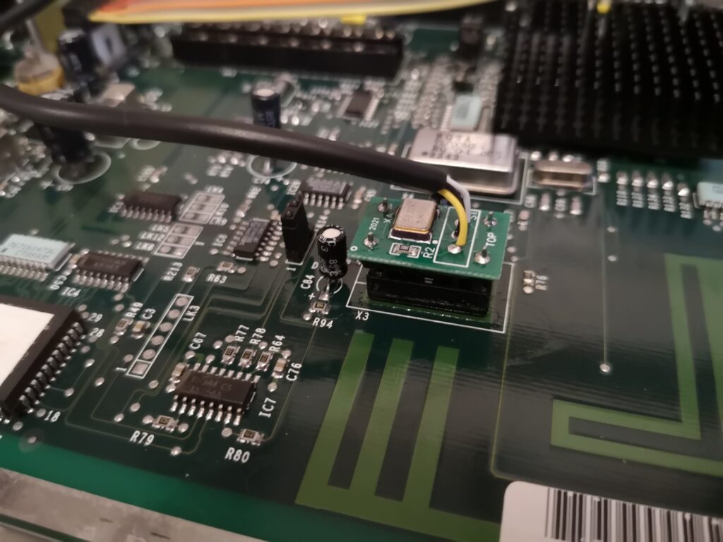
The following photo shows how the remote switch should be connected to the DualClock and how the DualClock should be installed.
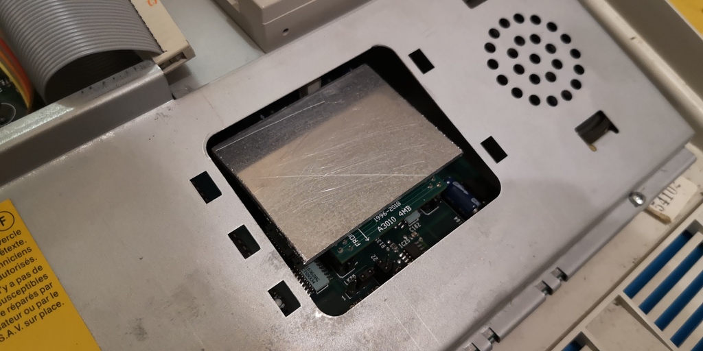
To mount the speed selection switch in my A3010, I made a cover for the podule bay from a piece of aluminium. I used a rectangle of 1.2mm thick aluminium with a length of 174mm and a width of 30mm. There are screws with the switches (on the front face, each side of the toggle itself) which can be placed through a cover to mount the switch securely.
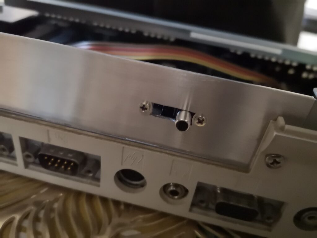
The following template can be used as a guide for making a podule cover, note that the exact location of the switch isn’t critical (hence not being dimensioned), but it is best if it is located in line with the lump on the back of the case as this protects the switch a little. Note I had to file the slot for the switch (dimensioned 14mm) quite close to the screw holes to get the switch to fully go into all three positions. When the switch is in position, a small ball bearing is visible in a slot on the body of the switch. Only one of these will be visible as the other will be out of site on the underside of the switch.
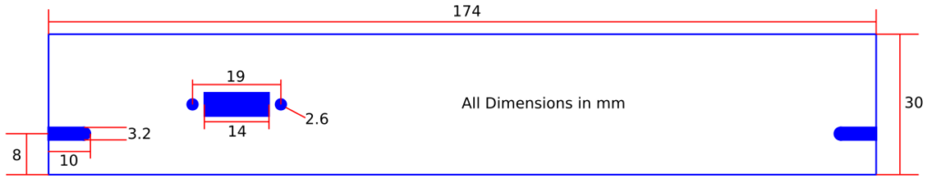
The cover can be mounted using two M3 machine screws (mine are 10mm long) and two M3 nuts. If the original switch mounting screws are misplaced, they are M2.5 by 2.5mm.
Fitting Heatsinks
I used a 40x40mm headsink on the SOC, and a custom aluminium heatsink on my RAM. To attach them, I used thermally conductive adhesive, specifically a product called “AG ThermoGlue” which I bought from eBay.
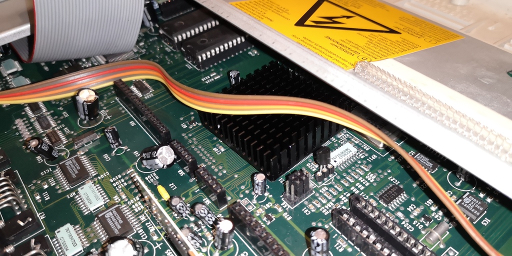
For the SOC, I cleaned both the SOC and heatsink with IPA. I then smeared some of the thermally conductive glue on the ARM250 and spread it around over the full surface. I then placed the heatsink on top and slid it in circles until it got a little more difficult to do so.
For the RAM I cleaned the heatsink and RAM chips, then fitted the heatsink with the metal RF shield in place to make sure that it didn’t clash with the heatsink. I placed a thin dotted line of (not too much!) thermally conductive glue on each RAM chip. I then placed the aluminium heatsink on top in a landscape orientation and pushed it in circles to spread the glue around evenly over the surface. I made sure that the heatsink was far back enough that it was below the surface of the RF shield to make sure that it didn’t protrude through the opening and clash with the keyboard, while making sure that it wasn’t so far back that it touched anything further back inside the computer.
I then left them to set, making sure to leave the computer level for the next few days.