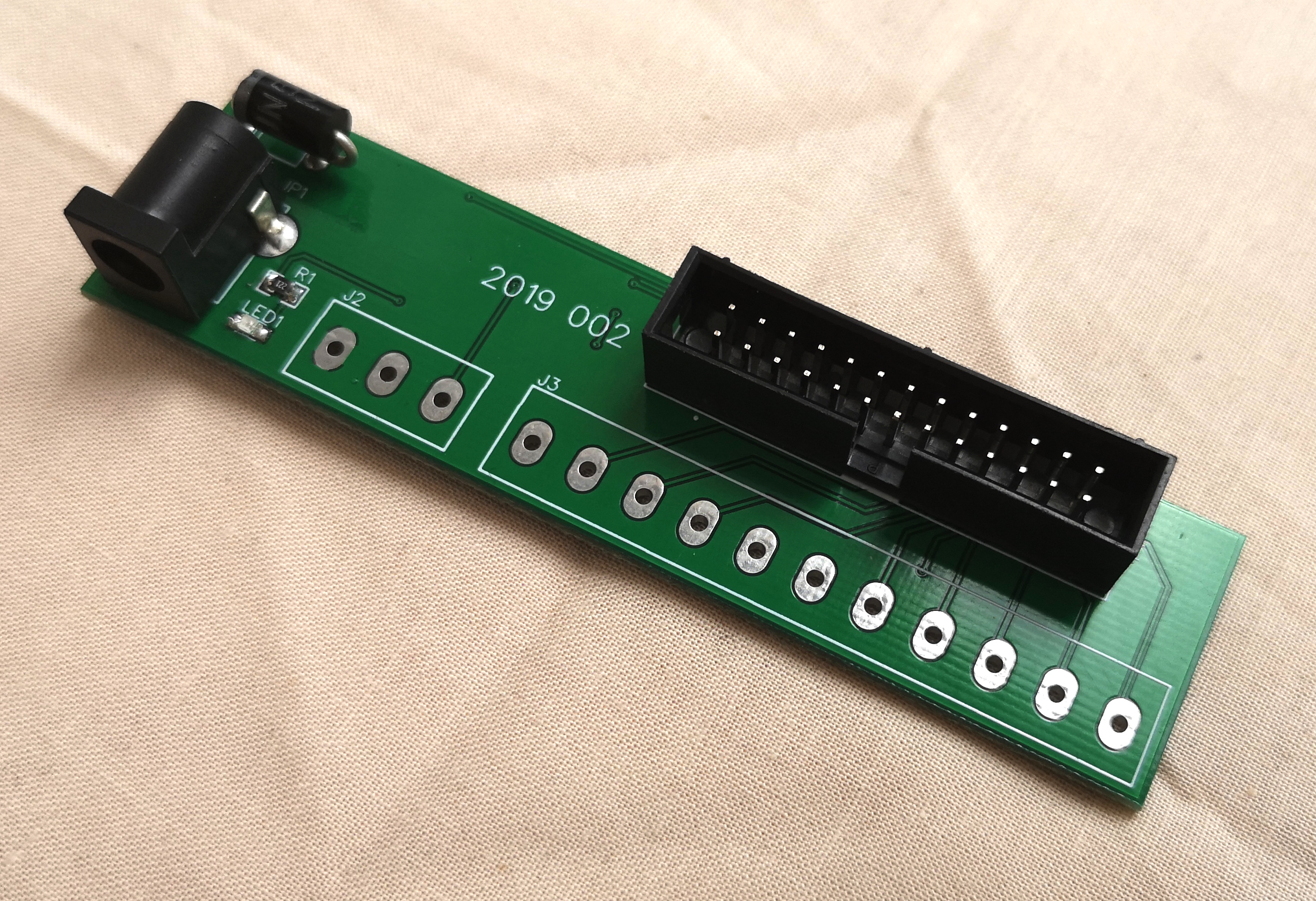
Having bought an Atomic Pi Single Board Computer (SBC), and faced with the issue that they need to be powered from a 2×13 female header on the underside of the board, I decided that I’d like an adapter to let me use a standard barrel jack power supply. Given that I’m based in the UK, it proved tricky / expensive to obtain the official “baby” breakout board, so I designed my own based on it. This version breaks out all of the same pins etc, although the orientation of the 3 pin power header is reversed.
When connecting the board, ensure that the key is aligned correctly as in the following photograph.
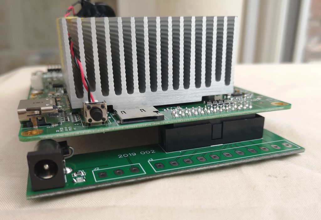
To hold the total board level, I have fitted PCB standoffs to the far end of the Atomic Pi board although some kind of case would be ideal. Take care not to short the underside of either the power adapter board, or the Atomic Pi itself.
Power is provided into the centre positive 5.5×2.1mm barrel jack, or optionally through an unpopulated 3 pin screw terminal. If using the screw terminal, it is also possible to provide 12v (to the right most of the 3 pins in the orientation of the image above) to the board. This allows for greater levels of amplification using the internal sound outputs. I have not used this myself yet as I have been using HDMI sound.
Please note that sometimes my Atomic Pi is very slow booting. If nothing happens immediately, wait at least a minute, possibly two. Once when I had installed a new operating system to the emmc, it was several minutes (with just a blinking cursor) before the machine booted.
The board pinout is as follows :
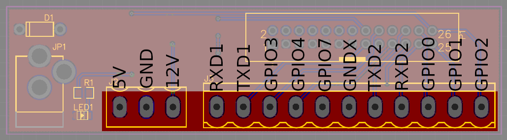
The on-board LED is connected to GPIO2 (as is the right most pin on the GPIO screw terminal connection – unpopulated by default). Turning the GPIO output off (low) causes the LED to light.
The following example python program will flash the LED. Note that the “cleanup code” causes the LED to remain on, so I have commented it out in this example, which is probably bad practice.
import atomicpi
import gpio as GPIO
import time
# Control by signal ID
GPIO_2=atomicpi.signals.ISH_GPIO_2.global_idx
GPIO.setup(GPIO_2), GPIO.OUT)
for x in range(10):
    GPIO.output(GPIO_2, False)
    time.sleep(0.5)
    GPIO.output(GPIO_2, True)
    time.sleep(0.5)
# the following line would perform "cleanup". Disabled as it turns the LED on.
#GPIO.cleanup(GPIO_2)
For simple testing and to ensure appropriate privileges are available to access the GPIO pins, the code above should be run as root or using “sudo”. For example, if the code has been saved in a file called “gpio.py” in the current directory, then you might run it from the terminal using :
sudo python ./gpio.pyOther GPIO can be controlled using this method by substituting GPIO_2 for the target pin.